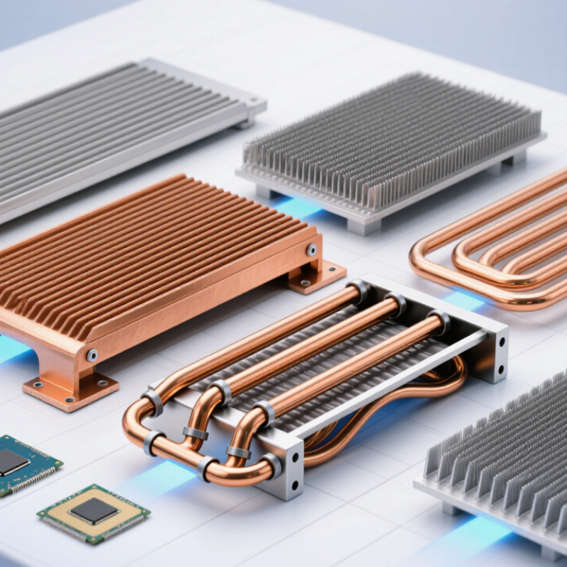
Choosing the best Cooling Heat Sink in 2026 requires more than comparing catalog dimensions or metal prices. Global buyers now face higher chip power, tighter enclosures, stricter energy targets, and unstable supply conditions. Aluminum extruded heat sinks remain practical for many standard devices. Copper models offer stronger heat transfer, but they add weight and cost. Vapor chambers and heat pipes can move heat across limited spaces. Bonded-fin and skived-fin designs may improve surface area where every millimeter matters.
Dr. Satish Kandlikar, a respected thermal-management researcher, has stated, “Thermal management is critical to the reliability of electronic systems.” That principle guides this review. A heat sink is not successful because it looks substantial. It must control junction temperature under real workloads, airflow restrictions, dust exposure, and repeated thermal cycling. Small details matter. Fin spacing, mounting pressure, interface material, fan direction, and surface treatment can change field performance. Test conditions matter too.
No ranking fits every buyer.
A low-cost aluminum design may outperform copper when airflow is strong and volume is high. A premium vapor chamber may disappoint if installation pressure is uneven. These are easy mistakes. This guide compares leading Cooling Heat Sink types through thermal resistance, durability, manufacturability, weight, maintenance, and total ownership cost. It also considers regional sourcing, certification expectations, packaging, and after-sales support. Some conclusions remain conditional, because real equipment rarely matches laboratory conditions. Buyers should verify thermal data with application-specific testing before placing large orders.
A heat sink is a passive thermal device placed against a hot electronic component. It transfers heat through a solid interface, usually from a chip into a metal base. Fins then spread that heat across a larger surface area. Air carries energy away as it moves through the fin channels. Natural convection works quietly, but forced airflow removes heat faster. Radiation contributes slightly, although it is rarely the main cooling path in compact electronics.
The International Energy Agency reported that data centres used about 415 terawatt-hours of electricity worldwide in 2024. It projects demand could approach 945 terawatt-hours by 2030. More computing means more heat at the component level. Material choice matters. Copper conducts heat at roughly 400 W/m·K, while aluminium is near 205 W/m·K under common reference conditions. These values come from established engineering property data, not marketing claims. The JEDEC JESD51 measurement standards also show why interface resistance must be measured carefully. A thin layer of poorly applied thermal compound can undermine an excellent fin design. Small gaps are not harmless.
In practical selection, buyers should inspect base flatness, fin spacing, airflow direction, mounting pressure, and the component’s thermal design power. A dense fin stack may perform well in a laboratory. It can struggle badly when dust blocks airflow. My early estimates often focused too heavily on material conductivity. That was incomplete. Real cooling depends on the entire thermal path, including contact quality and the surrounding enclosure.
2026 Best Cooling Heat Sink Types for Global Buyers
Main Heat Sink Types for Different Cooling Requirements
Choosing a heat sink starts with heat load, airflow, space, and assembly cost. Extruded aluminum suits general processors and power modules. Its straight fins provide predictable airflow and easy production. Stamped fins are lighter and economical, but their thermal performance can fall in crowded enclosures. For compact, high-flux devices, skived copper and vapor chambers spread heat across a wider surface.
The International Energy Agency reported that data centers consumed about 415 TWh of electricity in 2024. Cooling demand will increase as artificial intelligence hardware becomes denser. Heat-pipe assemblies work well when heat must move from a confined source to a remote fin stack. Vapor chambers offer better spreading across thin devices. Liquid cold plates handle the highest loads, especially where air cooling becomes impractical. However, pumps, seals, maintenance, and coolant compatibility require careful review.
Tips: Measure thermal resistance under real airflow, not laboratory assumptions. Check fin orientation inside the final chassis. Use thermal interface material with controlled thickness. A small gap can create a large temperature rise. Select copper for heat spreading, aluminum for lower weight and cost. Still, no catalog chart replaces testing. Early prototypes may reveal noise, pressure drop, or mounting problems that simulations miss. IEA, Energy and AI, 2025.
Cooling heat sinks in 2026 will be judged by materials, fin geometry, and real thermal behavior, not appearance alone. Aluminum offers low weight, corrosion resistance, and efficient production for many electronics. Copper spreads heat faster, but it adds cost and mass. Hybrid designs can balance both. The material choice should match the heat source, enclosure, and shipping requirements.
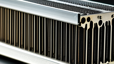
Fin design controls how air moves across the surface. Extruded fins suit reliable, moderate-power equipment with steady airflow. Skived fins create narrow channels and increase surface area without adding separate joints. Stamped fins remain practical for compact products. Pin-fin structures perform well when airflow changes direction. Some results disappoint. Dense fins may trap dust or create excessive pressure loss.
Thermal performance depends on more than rated conductivity. Engineers should check thermal resistance, contact pressure, interface material, fan performance, and ambient temperature. A one-degree improvement in a laboratory test may disappear inside a sealed cabinet. Testing at 25°C alone can mislead global buyers. Evaluate the heat sink at higher ambient conditions, expected airflow, and continuous load. Measure the base temperature and the hottest fin area. Mounting flatness matters too. A thin gap can weaken heat transfer significantly. Practical selection requires documented test methods, repeatable measurements, and honest attention to manufacturing variation. No fin design wins every application.
Materials, fin designs, and thermal performance factors
2026 Best Cooling Heat Sink Types for Global Buyers
Choosing a heat sink for global applications requires more than comparing thermal resistance. Start with the device power, allowable junction temperature, and local ambient conditions. A 10°C lower ambient temperature can significantly change the required design. Extruded aluminum suits cost-sensitive electronics with steady airflow. Copper or vapor-chamber designs work better when heat density is high. Stamped fins remain practical for compact, high-volume products.
The International Energy Agency’s Electricity 2024 report estimates that data centers used about 240–340 TWh globally in 2022. It also projects demand could reach 620–1,050 TWh by 2026. This pressure makes efficient thermal design more important, especially for servers, telecom equipment, and industrial controls. Check airflow direction, fan pressure, dust exposure, altitude, humidity, and maintenance access. A fin layout that performs well in a clean laboratory may clog quickly in a dry factory.
Field experience shows that interface material often limits real performance. Measure contact flatness, mounting pressure, and thermal cycling behavior. Review applicable IEC requirements and confirm material compliance before production. Select aluminum for lighter shipping and easier machining, but consider copper inserts for concentrated heat. Corrosion protection may be necessary near coastal markets. I have seen designs fail because engineers trusted catalog data too much. That shortcut can fail. Test prototypes under the hottest realistic conditions, then repeat testing after vibration and aging.
2026 Best Cooling Heat Sink Types for Global Buyers
Manufacturing Standards, Testing, and Buyer Evaluation Criteria
A reliable heat sink starts with controlled manufacturing, not attractive fins alone. Suppliers should maintain documented quality procedures, preferably aligned with ISO 9001 principles. Buyers should verify aluminum grade, copper purity, surface treatment, and dimensional tolerances. Check fin thickness, base flatness, mounting-hole position, and burr removal. Small deviations can create uneven contact and higher thermal resistance.
Thermal performance testing should use a repeatable setup. Record heat load, ambient temperature, airflow speed, interface material, and mounting pressure. Results should include thermal resistance, temperature rise, and pressure drop where airflow matters. Test reports need sample identification and calibration records. A single impressive result is not enough. Test conditions often explain the difference.
Tips: Request a production sample, drawing, material certificate, and complete test method. Compare results under identical conditions. Inspect the base with a flatness gauge, not only by sight. Ask how anodizing thickness and coating adhesion are checked. For liquid-cooled designs, review leak testing, flow rate, and corrosion resistance. For finned air coolers, examine fan compatibility and acoustic limits. Standards help, but they do not replace engineering judgment. No test is perfect. A supplier may report excellent laboratory data, yet actual equipment can run hotter because airflow is restricted. Buyers should leave safety margin for dust, assembly variation, and aging.
| Heat Sink Type | Typical Material and Thermal Conductivity | Manufacturing Process | Typical Cooling Characteristics | Key Manufacturing Standards and Controls | Recommended Testing and Inspection | Buyer Evaluation Criteria |
|---|---|---|---|---|---|---|
| Extruded Aluminum Heat Sink |
Aluminum 6063-T5 or 6063-T6 Approximately 200 W/m·K at room temperature |
Direct extrusion of a finned profile, followed by cutting, deburring, drilling, tapping, anodizing, or other surface treatment. | Cost-effective and widely available. Suitable for natural convection and forced-air cooling. Typical fin heights are approximately 10–100 mm, depending on profile complexity and extrusion capability. |
Dimensional tolerances
Fin straightness
Surface finish
Material traceability Aluminum temper and chemical composition should be confirmed through material certificates. |
Dimensional inspection using calibrated gauges or CMM; visual inspection for cracks and die lines; coating thickness testing where anodized; thermal-resistance testing under defined airflow and power conditions. | Check fin thickness, fin pitch, flatness of the mounting base, burr control, maximum extrusion length, anodizing consistency, and packaging protection against fin deformation. |
| Skived Copper Heat Sink |
High-purity copper, commonly C110 or equivalent Approximately 390–400 W/m·K at room temperature |
Thin fins are cut and raised from a solid copper block using a skiving tool, creating an integral base-and-fin structure without a separate fin-to-base joint. | High thermal spreading capability and low joint resistance. Effective for high heat flux and compact assemblies. Heavier and generally more expensive than aluminum designs. |
Copper composition
Fin integrity
Base flatness
Burr control Control of fin thickness, fin height, and fin-to-fin spacing is essential. |
Copper material verification; fin-height and pitch measurement; base flatness measurement; pull or handling checks for fin durability; thermal cycling and thermal-resistance testing. | Evaluate weight, corrosion protection, fin fragility, mounting pressure limits, allowable base roughness, and compatibility with the mating component and thermal interface material. |
| Bonded-Fin Heat Sink |
Aluminum or copper base with aluminum or copper fins Base conductivity depends on selected material; aluminum is typically around 200 W/m·K and copper around 390–400 W/m·K |
Separately produced fins are bonded to a machined, extruded, or stamped base using thermal epoxy, brazing, soldering, or another qualified joining method. | Allows taller or denser fins than many extrusion profiles. Suitable for forced-air cooling and large surface-area requirements. Joint quality strongly affects thermal performance. |
Bond-line control
Joint coverage
Cure or brazing profile
Fin alignment Joining-process parameters must be documented and repeatable. |
Visual inspection of bond coverage; bond-line thickness measurement; shear or pull testing on sample assemblies; thermal cycling; vibration testing where required; thermal-resistance testing. | Request evidence of joint reliability, adhesive operating-temperature limits, void-control capability, fin alignment, repairability, and long-term resistance to vibration and thermal cycling. |
| Stamped Sheet-Metal Heat Sink |
Aluminum or copper sheet Typical conductivity is approximately 200 W/m·K for aluminum and 390–400 W/m·K for copper |
Progressive stamping, forming, piercing, and bending from sheet stock. The design may include folded fins, spring clips, or integrated mounting features. | Lightweight and economical for low-to-moderate heat loads. Best suited to space-constrained electronics, small power devices, and airflow-assisted applications. |
Sheet thickness
Bend radius
Burr height
Forming accuracy Spring force and fatigue performance should be controlled when clips are integrated. |
Sheet-thickness verification; dimensional and burr inspection; clip-force testing; coating inspection; temperature-rise testing under representative airflow and mounting conditions. | Confirm contact pressure, electrical isolation requirements, spring retention, sharp-edge control, repeatability at production volume, and suitability for automated assembly. |
| Die-Cast Aluminum Heat Sink |
Aluminum casting alloys such as A356 or similar grades Typical thermal conductivity is approximately 90–170 W/m·K, depending on alloy and casting condition |
High-pressure or gravity die casting, followed by trimming, machining, drilling, tapping, and surface treatment where necessary. | Supports complex shapes, integrated mounting features, and high-volume production. Generally has lower thermal conductivity than wrought aluminum and may contain casting porosity. |
Alloy verification
Porosity control
Wall thickness
Die condition Casting process parameters and inspection sampling should be defined. |
Chemical composition testing; dimensional inspection; radiographic or computed-tomography sampling for critical porosity control; surface inspection; thermal-resistance and thermal-cycle testing. | Evaluate production quantity, casting yield, porosity risk beneath the mounting surface, machining allowance, coating adhesion, and total cost including tooling. |
| Forged Aluminum Heat Sink |
Wrought aluminum alloys such as 6061 or 6063 Approximately 170–235 W/m·K, depending on alloy, temper, and direction |
Heated or cold forging forms the base and fin structure, followed by trimming, machining, and surface finishing. | Good structural strength, low porosity, and reliable thermal contact. Suitable for rugged applications and moderate-to-high heat loads where mechanical durability is important. |
Forging temperature
Grain flow
Flash removal
Heat treatment Control of final temper and dimensional stability is important. |
Alloy and temper verification; dimensional inspection; hardness testing; surface crack inspection; base-flatness measurement; thermal cycling and vibration testing. | Compare tooling investment with expected volume, verify mechanical load capability, review grain-flow requirements, and confirm that the formed fins meet the airflow and cleaning requirements. |
| Vapor-Chamber Heat Sink Assembly |
Copper vapor chamber with internal wick structure and working fluid Copper casing typically provides approximately 390–400 W/m·K, while effective thermal performance depends on phase-change design |
Fabrication of sealed copper chambers, wick installation, controlled evacuation, working-fluid charging, sealing, and attachment to a fin stack or graphite spreader. | Excellent heat spreading for localized high-power sources and thin devices. Can reduce hot spots and transfer heat to a larger fin area. Orientation and allowable heat load must be characterized. |
Hermetic sealing
Internal cleanliness
Charge control
Leak prevention The internal working fluid and pressure system require controlled production procedures. |
Helium or equivalent leak testing; vacuum and pressure verification; X-ray or other non-destructive inspection where appropriate; thermal performance mapping; power-step, thermal-cycle, and orientation testing. | Review start-up temperature, maximum heat load, thickness tolerance, flatness, orientation sensitivity, leak-rate specification, warranty conditions, and integration with the thermal interface layer. |
| Liquid Cold Plate |
Aluminum or copper plate with machined, brazed, friction-stir-welded, or formed internal channels Aluminum is typically around 200 W/m·K; copper is typically around 390–400 W/m·K |
CNC machining, vacuum brazing, friction-stir welding, extrusion, or bonded-channel construction. Includes fluid ports and sealing components. | Supports high heat removal when connected to a controlled coolant loop. Performance depends on coolant flow rate, pressure drop, channel design, and coolant properties. |
Pressure boundary
Channel dimensions
Cleanliness
Weld or braze quality Material compatibility and corrosion control must be addressed. |
Hydrostatic or pneumatic pressure testing; helium leak testing for critical systems; flow-rate and pressure-drop testing; thermal-resistance testing; corrosion and thermal-cycle testing. | Check rated pressure, burst margin, coolant compatibility, pressure drop, port configuration, sealing method, contamination limits, serviceability, and compliance with the system safety requirements. |