Leave Your Message
Choosing a Solid State Relay manufacturer is about more than comparing prices. The right device must match the load, control signal, switching method, and operating environment. A relay handling a small heater may not suit a motor or industrial oven. Check rated voltage and current, leakage current, isolation, and expected cycle life. Thermal details matter. A compact relay may still require a heat sink and clear airflow. Poor heat management can shorten service life or cause nuisance shutdowns. These practical checks help buyers look beyond catalog claims.
This guide introduces ten manufacturers for global buyers to evaluate. It considers product range, technical documentation, application support, and availability. The manufacturers are options to investigate, not a universal ranking. Buyers should confirm specifications against the intended load and installation. Ask about relevant certifications, sample testing, lead times, and replacement availability. A technically suitable relay also needs dependable documentation and responsive engineering support. Availability varies by region. Support can be uneven. That deserves attention. Product ranges change, and published specifications may not cover every configuration or production revision. Treat this list as a starting point, then validate each choice with current datasheets and, where practical, testing. The best Solid State Relay is the one that performs reliably in your system.
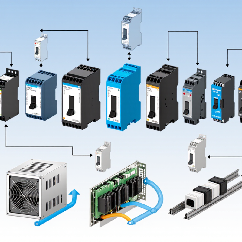
Solid-state relays switch electrical loads electronically, without moving contacts. A control signal drives semiconductor devices, such as thyristors for AC loads or MOSFETs for DC loads. No contact bounce. Yet “wear-free” does not mean loss-free: leakage current and voltage drop across the output create heat. In a control cabinet, an SSR mounted beside a warm motor drive may need spacing, thermal derating, or a heatsink.
IEC 62314:2006 provides general requirements for solid-state relays intended for industrial applications. Buyers can use it as a shared reference when comparing operating characteristics, ratings, and verification conditions. Check the exact load type, switching mode, ambient temperature, and cooling assumptions; a headline current rating alone can mislead. Zero-cross switching can reduce electrical disturbance on suitable AC loads, while random-turn-on versions suit other control needs. Details matter.
The semiconductor supply chain is large, but that does not guarantee identical relay performance. The Semiconductor Industry Association’s 2025 report, drawing on WSTS data, recorded global semiconductor sales of 627.6 billion US dollars in 2024, up 19.1% year over year. That figure describes the wider chip industry, not SSR production. A useful comparison still starts with application data: load current, inrush, switching frequency, and cabinet temperature. Datasheets do not always make thermal assumptions easy to spot. Ask for test conditions, then check whether they resemble the installation.
A practical, technology-based comparison framework for evaluating solid state relay (SSR) suppliers. The rows are selection criteria, not a ranked list of manufacturers.
| No. | Comparison Dimension | What Buyers Should Check | Technical Context | Relevance to IEC 62314:2006 |
|---|---|---|---|---|
| 1 | Output switching technology | Confirm whether the output is intended for AC loads or DC loads, and identify the output semiconductor type. | AC-output SSRs commonly use thyristors or triacs; DC-output SSRs commonly use transistor-based switches such as MOSFETs. An AC-output device is not automatically suitable for switching DC. | Check the device's stated ratings and test documentation against the applicable solid-state relay requirements. |
| 2 | Switching mode | Determine whether the relay uses zero-cross switching or random (instant-on) switching. | Zero-cross switching turns an AC load on near the AC waveform's zero crossing. Random switching can turn on at other points in the waveform and may be needed for phase-control applications. | Use the manufacturer's declared operating characteristics and test evidence when assessing suitability. |
| 3 | Input-control compatibility | Verify the control-input voltage or current range, polarity where relevant, and compatibility with the controller's output. | SSR inputs may be designed for DC control or AC control. The control signal must stay within the device's specified input limits. | Compare declared input characteristics and relevant test results with the intended control circuit. |
| 4 | Load type and inrush current | Check compatibility with resistive, inductive, capacitive, lamp, motor, or other intended loads, including startup current. | Some loads draw substantially more current at startup than during normal operation. Switching behavior and load characteristics affect relay stress and service life. | Request application-specific ratings or guidance; a nominal current rating alone may not establish suitability for every load. |
| 5 | Voltage and current ratings | Compare rated load voltage and current with the system's normal and foreseeable operating conditions. | Ratings depend on the specific device and operating conditions. Buyers should also check permitted voltage transients and any stated derating requirements. | Confirm that rating declarations and supporting documentation correspond to the applicable product standard and intended use. |
| 6 | Thermal management | Review on-state losses, permitted ambient temperature, mounting instructions, and heatsink requirements. | Semiconductor output devices dissipate heat while conducting. Actual load current may need to be reduced as ambient temperature or thermal resistance increases. | Assess the relay under its declared mounting and operating conditions, using the manufacturer's thermal data. |
| 7 | Off-state leakage and switching behavior | Check off-state leakage current, minimum load considerations, and any load-specific behavior when the output is commanded off. | Unlike an open mechanical contact, a semiconductor output can allow a small off-state current. This may matter for sensitive loads or high-impedance monitoring circuits. | Use the declared electrical characteristics and relevant verification data to assess the application. |
| 8 | Input-to-output isolation | Review the specified isolation characteristics and the installation's insulation and safety requirements. | Many SSR designs provide electrical isolation between control and load circuits, but the applicable ratings and test conditions vary by product. | Check the manufacturer's documented isolation ratings and evidence against the requirements applicable to the installation. |
| 9 | Protection and failure behavior | Ask about overvoltage suppression, short-circuit protection, overload coordination, and expected failure behavior. | Protection features are product-specific. Semiconductor relays can fail in different ways, so system-level fusing and protection should not be assumed to be built in. | Review declared protection features and test documentation; design external protection for the complete circuit. |
| 10 | Standards documentation and traceability | Request the exact standard edition, test reports or certificates where applicable, ratings, datasheets, and production traceability information. | IEC 62314:2006 is the IEC standard titled “Solid-state relays.” A supplier's statement of compliance should be supported by documentation identifying the product and the basis of the claim. | Verify the edition and scope cited in the supplier's documentation and confirm that they match the relay and intended application. |
This table provides general purchasing guidance, not a manufacturer ranking or product certification. Confirm all ratings, applicable standards, and installation requirements using the specific relay's documentation.