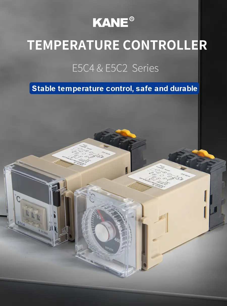


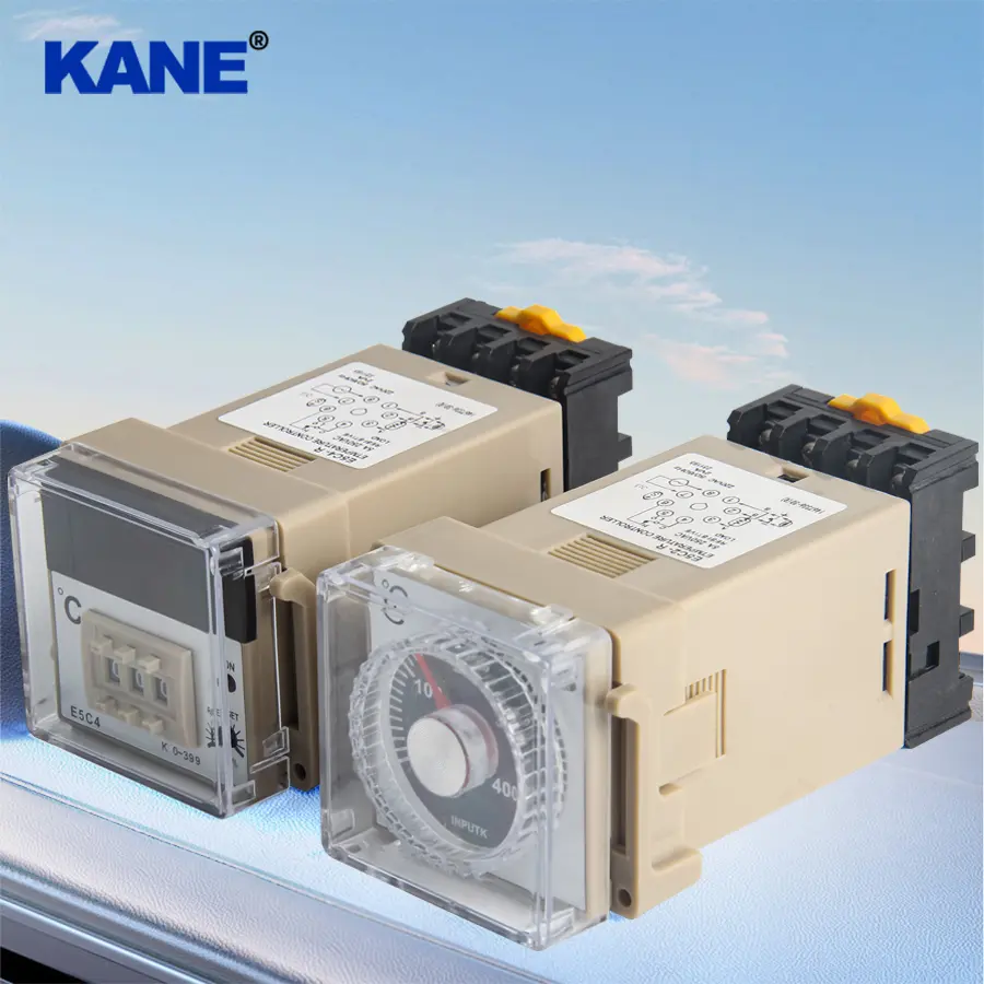
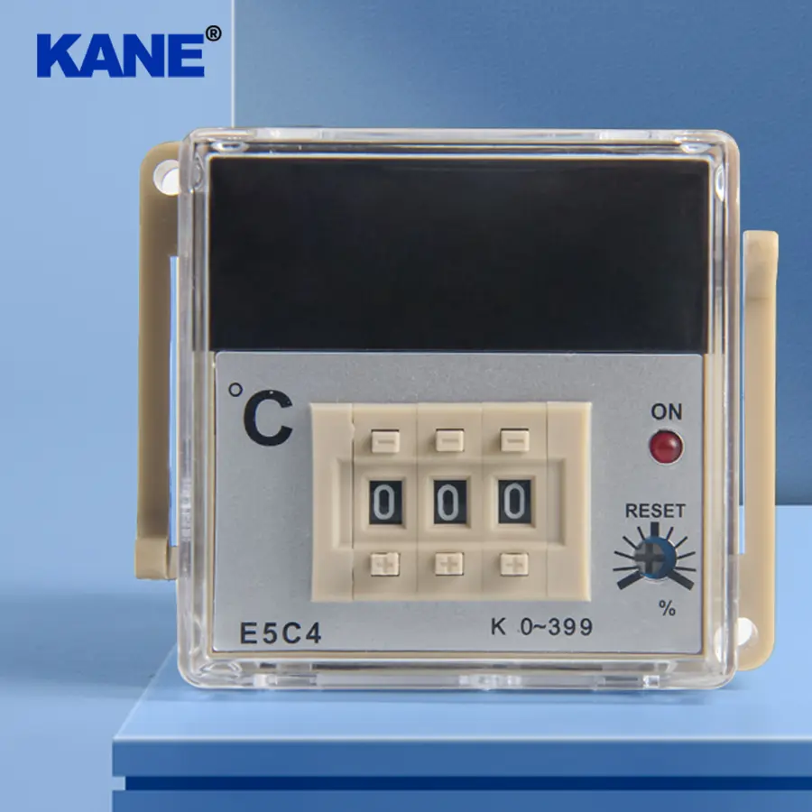

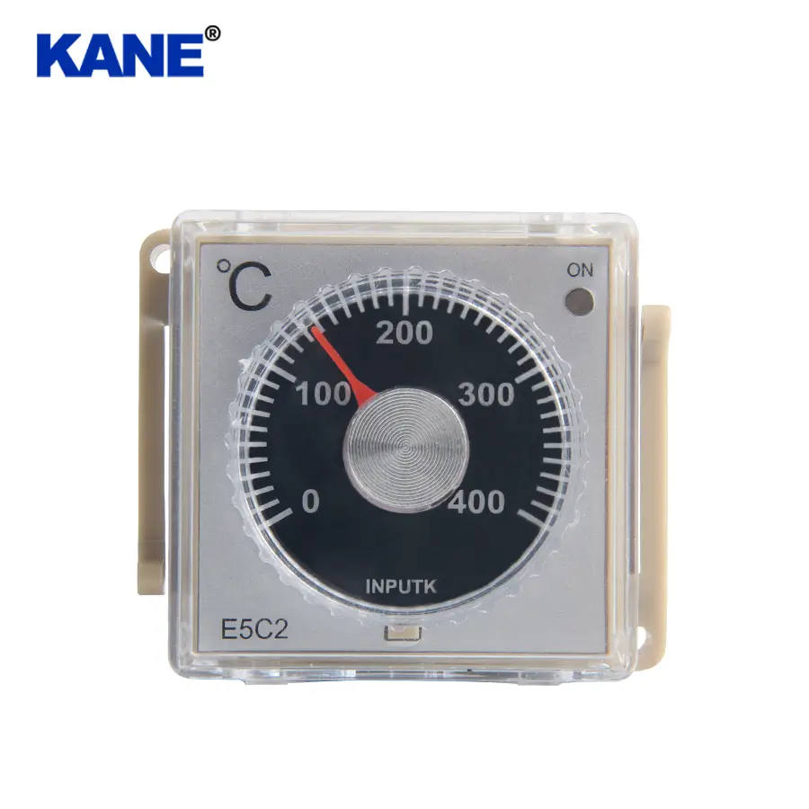
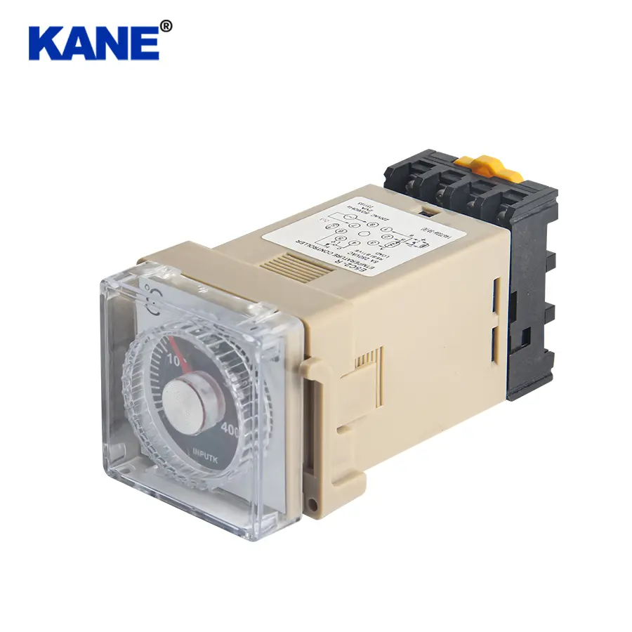
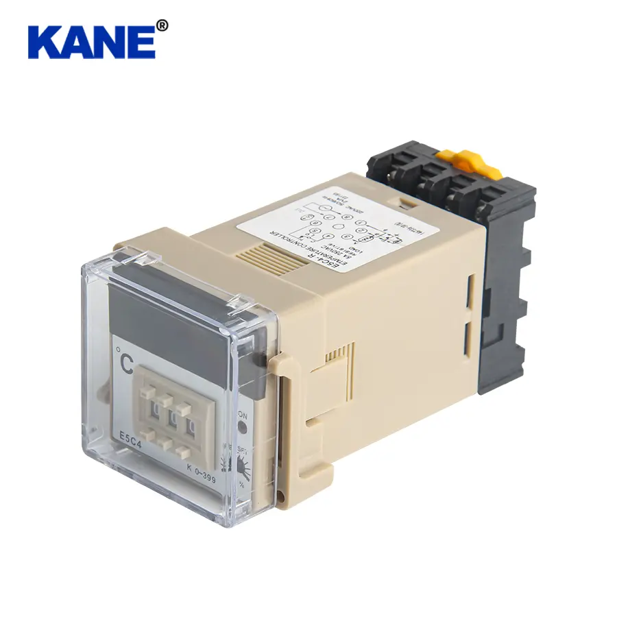
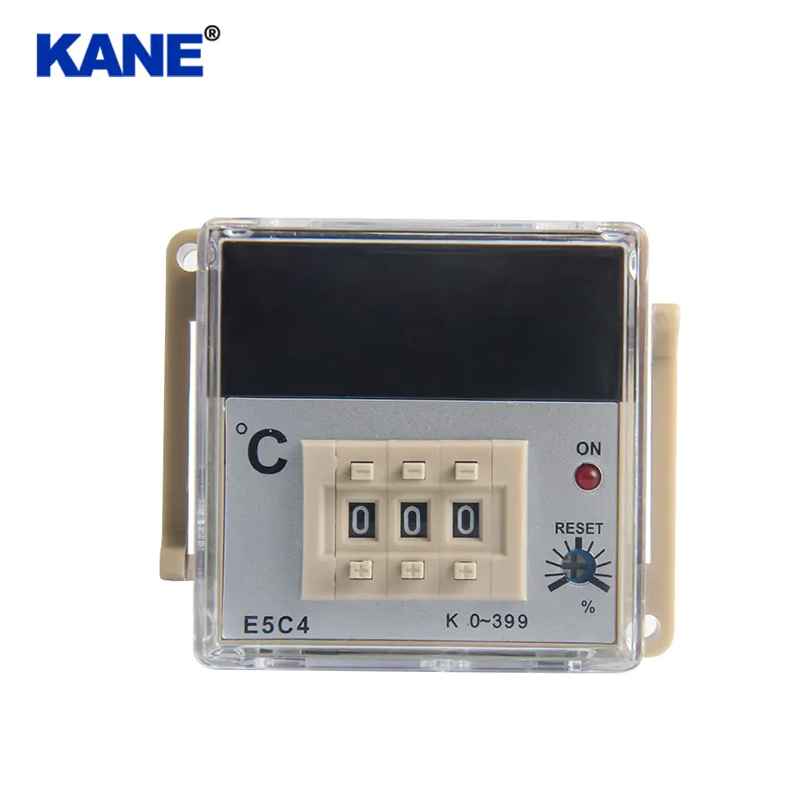
E5C4&E5C2 Series Temperature Controller with Analog Setting knob
Product Details
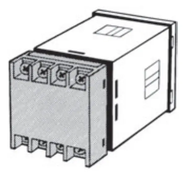
Detailed Picture

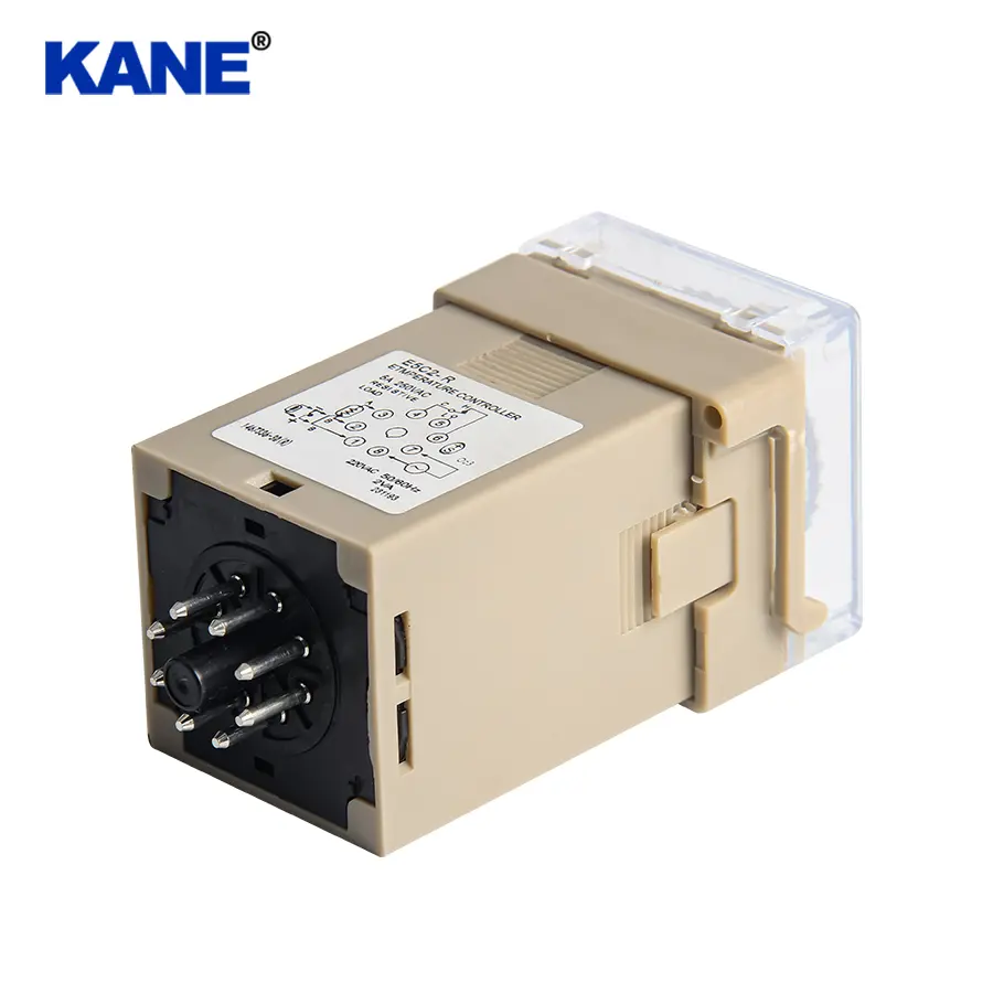
E5C2, E5C4 Series Temperature Controllers
Model Number Structure
■ Model Number Legend

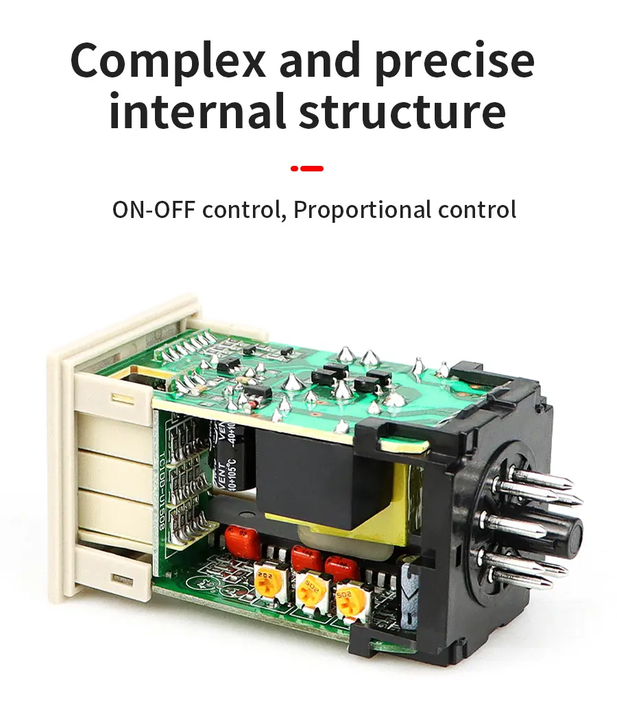
1.Control Outputs
R: Relay
2.Control Method
20: ON-OFF control
40: Proportional control
3.Input
K: K-type thermocouple
J: J-type thermocouple
P-D: Platinum resistance thermometer (Pt100)
G: Thermistor with replaceable element
Note: A functional explanation is provided here for illustration, but models are not necessarily available for all possible combinations. Refer to Ordering Information when ordering.
Examples
1.Relay control output, ON/OFF control, type-K thermocouple input: E5C2-R20K
2.Relay control output, proportional control, thermocouple input: E5C2-R40P-D
Ordering Information
■ Temperature Controllers
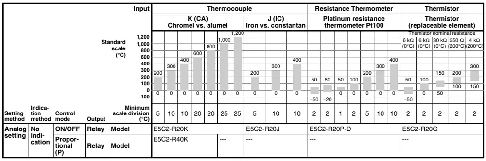
Note: When placing an order, specify the temperature range in addition to the model number.
Standard Models
|
|
|
|
Indication method |
No indication |
|
|
|
|
|
Control mode |
ON/OFF |
Proportional(P) |
|
|
Input |
|
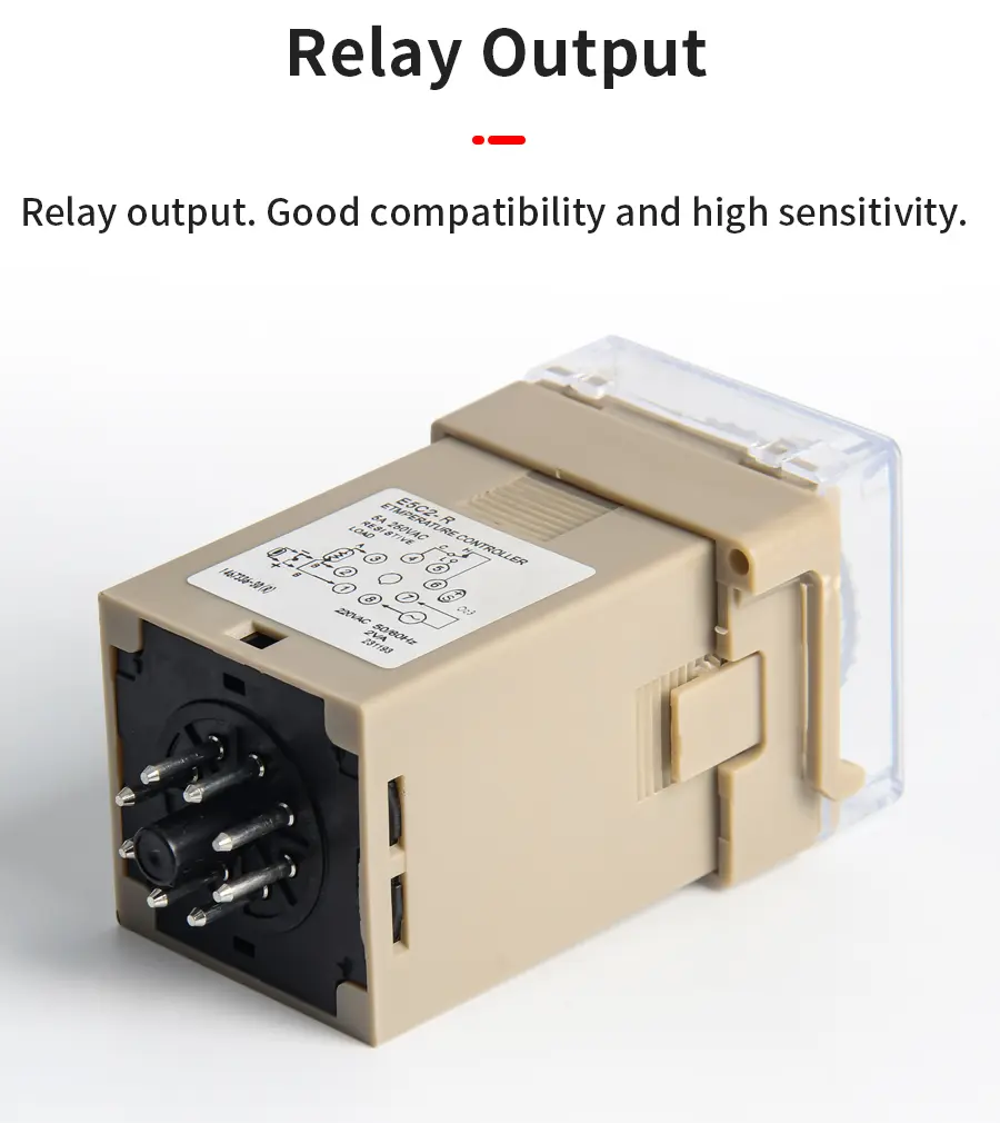
Output |
Relay |
|
|
Input/standard scale(℃) |
Thermocouple |
K (CA) |
0 to 200 |
E5C2-R20K |
E5C2-R40K |
|
0 to 300 |
E5C2-R20K |
E5C2-R40K |
|||
|
0 to 400 |
E5C2-R20K |
E5C2-R40K |
|||
|
0 to 600 |
E5C2-R20K |
E5C2-R40K |
|||
|
0 to 800 |
E5C2-R20K |
E5C2-R40K |
|||
|
0 to 1000 |
E5C2-R20K |
--- |
|||
|
0 to 1200 |
E5C2-R20K |
--- |
|||
|
J(IC) |
0 to 200 |
E5C2-R20J |
--- |
||
|
0 to 300 |
E5C2-R20J |
--- |
|||
|
0 to 400 |
E5C2-R20J |
--- |
|||
|
|
|
|
Indication method |
No indication |
|
|
|
|
Control mode |
ON/OFF |
|
|
Input |
|
Output |
Relay |
|
Input/standard scale(℃) |
Resistance Thermometer |
Platinum resistance thermometer Pt100 |
−50 to 50 |
E5C2-R20P-D |
|
−20 to 80 |
E5C2-R20P-D |
|||
|
0 to 50 |
E5C2-R20P-D |
|||
|
0 to 100 |
E5C2-R20P-D |
|||
|
0 to 200 |
E5C2-R20P-D |
|||
|
0 to 300 |
E5C2-R20P-D |
|||
|
0 to 400 |
E5C2-R20P-D |
|||
|
Thermistor |
THE (replaceable element) |
−50 to 50 |
E5C2-R20G |
|
|
0 to 100 |
E5C2-R20G |
|||
|
50 to 150 |
E5C2-R20G |
|||
|
100 to 200 |
E5C2-R20G |
|||
|
150 to 300 |
E5C2-R20G |
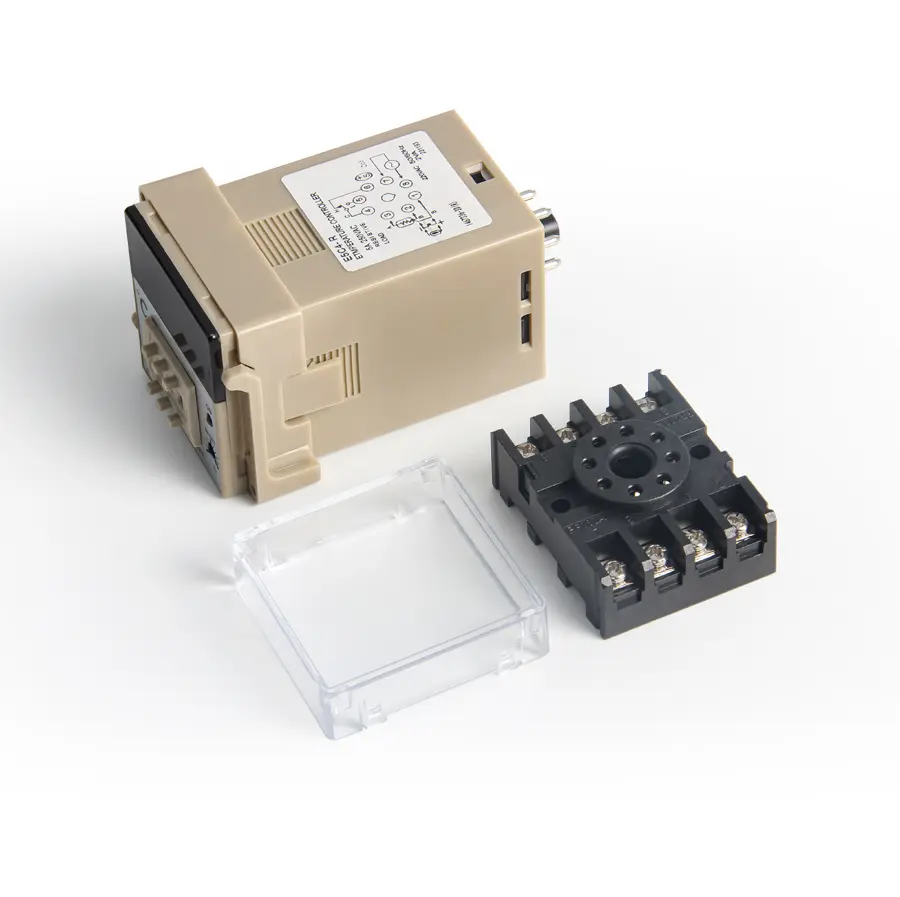
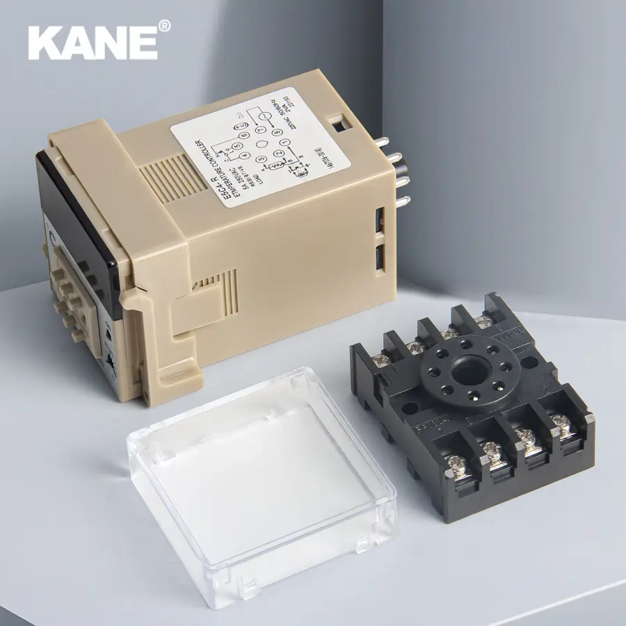
■ Accessories (Order Separately)
Sockets
|
Name |
Model |
|
Front Connecting Socket |
P2CF-08 |
|
Back Connecting Socket |
P3G-08 |
|
Front Connecting Socket with Finger Protection |
P2CF-08-E |
|
Protective Cover (for finger protection) |
Y92A-48G |
Protective Cover
|
Type |
Model |
|
Hard Protective Cover |
Y92A-48B |
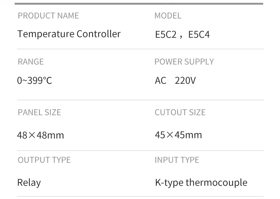
Specifications
■ Ratings
|
Supply voltage |
100 to 240 VAC 50/60 Hz |
|
Operating voltage range |
90% to 110% of rated supply voltage |
|
Power consumption |
Approx. 3.6 VA |
|
Input |
Thermocouple (with sensor burnout detection circuit), platinum resistance thermometer, or thermistor with replaceable element |
|
Control method |
ON/OFF or proportional control |
|
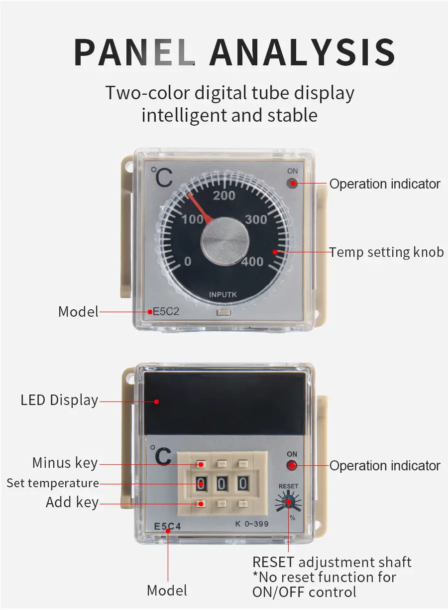
Setting method |
Analog setting |
|
Indication method |
No indication |
|
Control output |
Relay output:SPDT, 3 A at 250 VAC,resistive load (switching capacity: 330 VA) |
|
Ambient operating temperature |
−10°C to 55°C (with no icing or condensation) |
|
Ambient operating humidity |
45% to 85% |
Note: Do not use an inverter output as the power supply. (Refer to Safety Precautions for All Temperature Controllers.)
■ Characteristics
|
Setting accuracy |
±2% FS max.(Influence of EMS:±4% FS max.)(See note 1.) |
|
Hysteresis |
Approx. 0.5% FS (fixed) |
|
Proportional band |
3% FS (fixed) |
|
Control period |
Approx. 20s |
|
Reset range |
5±1% FS min.(See note 2.) |
|
Insulation resistance |
20 MΩ min.(at 500 VDC) |
|
Dielectric strength |
2,000 VAC,50/60 Hz for 1 min between charged terminals and uncharged metallic parts |
|
Vibration resistance |
Malfunction:10 to 55 Hz,0.15-mm single amplitude for 10 min each in X,Y,and Z directions |
|
Shock resistance |
Malfunction:147 m/s2,3 times each in 6 directions |
|
Life expectancy |
Electrical:100,000 operations min.(3 A at 110 VAC,resistive load) |
|
Weight |
Approx. 100 g(with flush-mounting adapter) |
|
Degree of protection |
Front panel:IEC standard IP40 (See note 3.) |
|
Applicable Socket |
P2CF-08 (order separately),P3G-08 (order separately) |
|
Applicable Protective Cover |
Y92A-48B (order separately) |
Note: 1. At EN 61326-1 (Industrial electromagnetic environment (EN/IEC 61326-1 Table 2))
2.No reset function is incorporated by any E5C2 model with ON/OFF control.The reset function is used to correct offset for proportional control. If there is an offset below the set value, turn the reset adjustment clockwise.
3.A special Watertight Cover is used to achieve this degree of protection (IP66, NEMA4). Refer to Y92A-□□N.
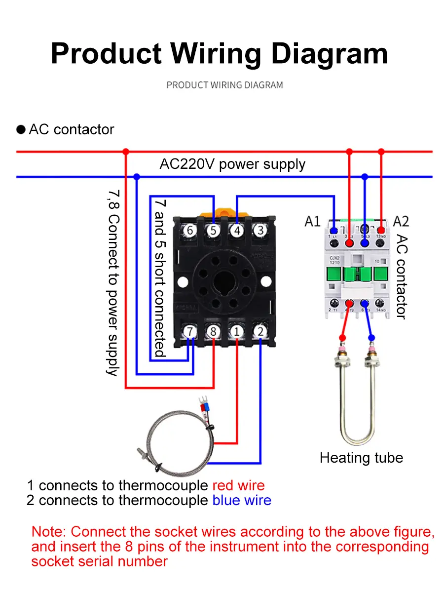
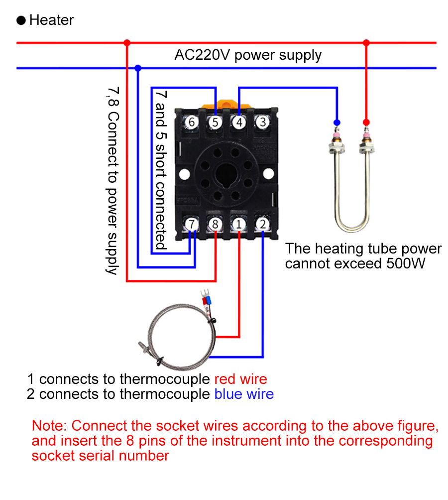
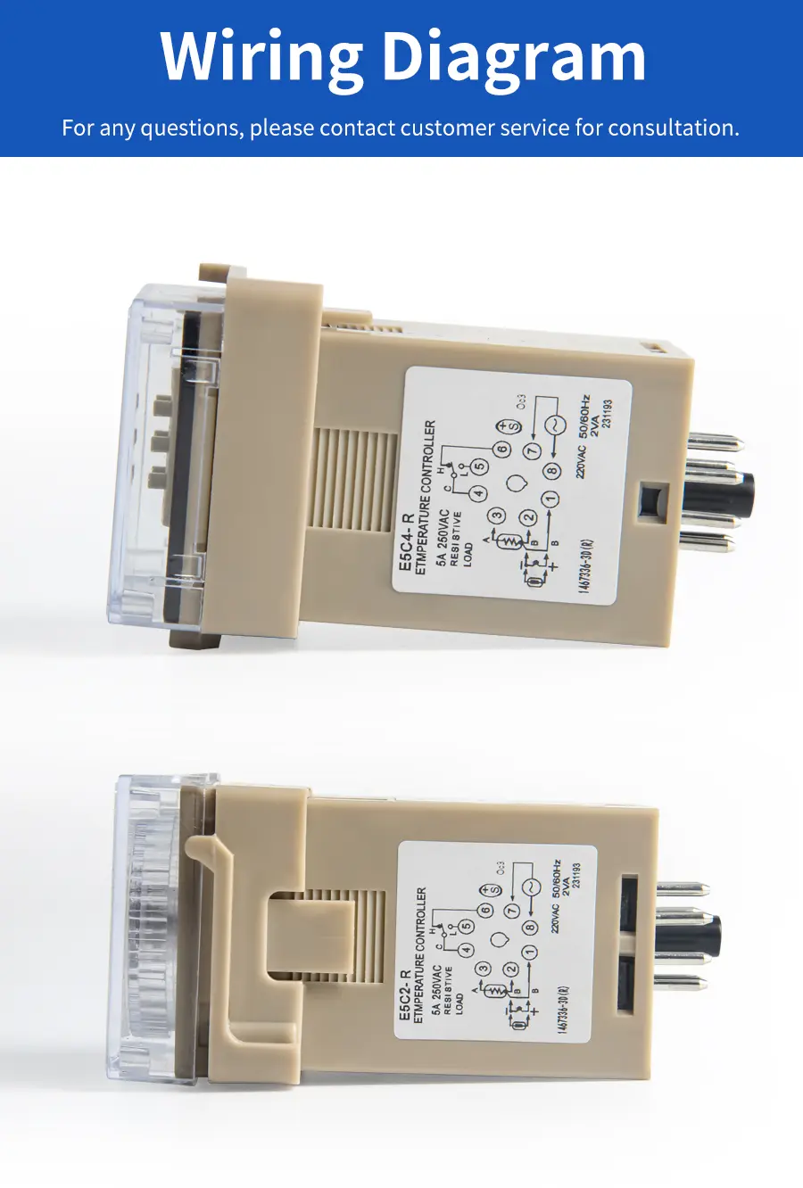
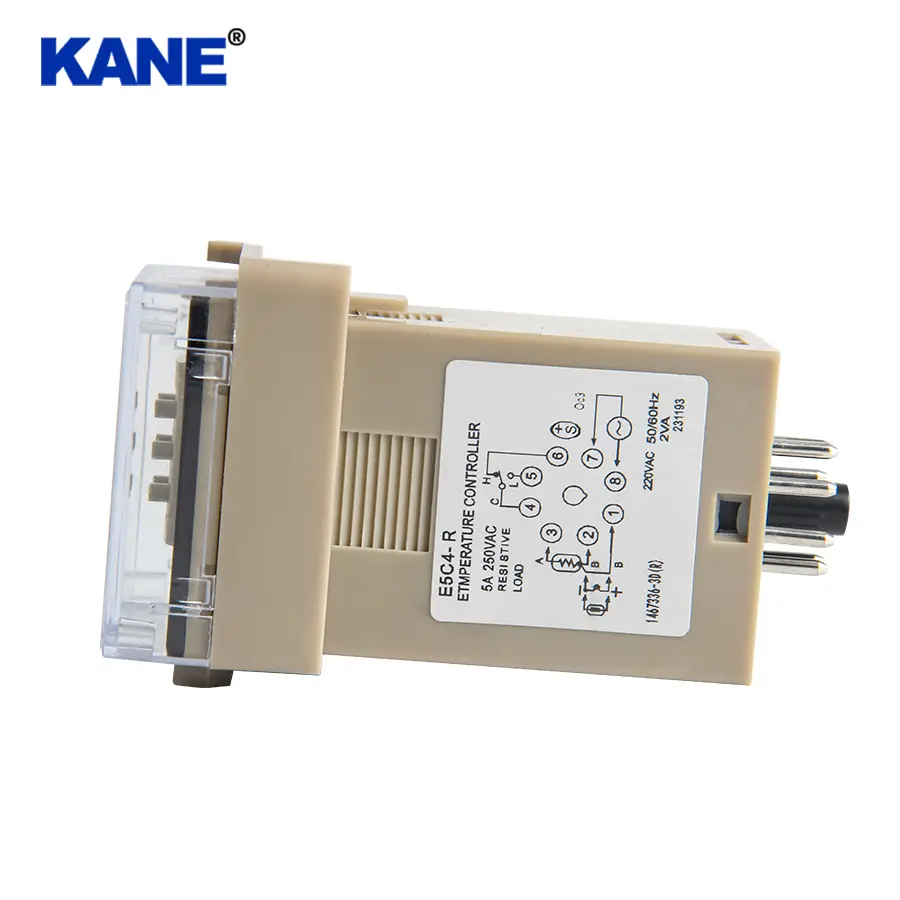
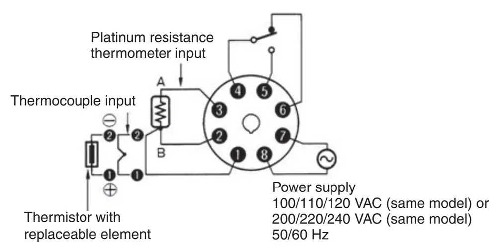
■ Connections
Connecting the Input
1.Connect a thermocouple, the E52-THE□Thermistor (replaceable element) or a platinum resistance thermometer to terminals 1 (positive) and 2 (negative) on the E5C2 as shown in thefollowing illustration.
2.On the E52-□□1D, the lead wires are thermocouple element wires, making them difficult to solder because solder will not stick to them easily. Remove the crimp terminal and polish the ends before attempting to solder them.
Output
1.If the load circuit is a heating control system,be sure to connect the load to terminals 4 and 5.If the load circuit is a cooling control system,be sure to connect the load to terminals 4 and 6.
2.We recommend using an external relay to extend the electrical life of internal relays whendriving a large capacity load. This is particularly important when the output relay is switched frequently (e.g., with proportional control).
Power Supply
1.If a single power supply is used for the E5C2 and the load, the supply voltage of the power supply may vary greatly when the load is open or closed if the capacity of the power supply is not large enough. Make sure that the capacity of the power supply is large enough so that the supply voltage range will be always from 90% to 110% of the rated supply voltage.
2.The E5C2 operates at either 50 or 60 Hz.
Operation Indicator
|
Indicator |
Output |
|
|
NO contacts (4 and 5) |
NC contacts (4 to 6) |
|
|
Red Lit |
ON |
OFF |
|
Not lit |
OFF |
ON |
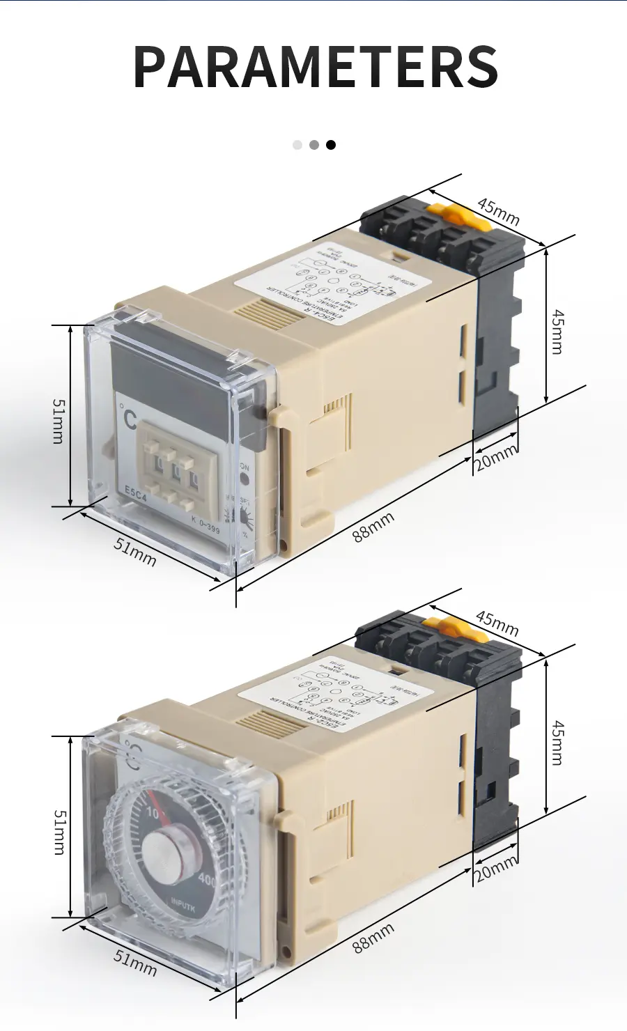
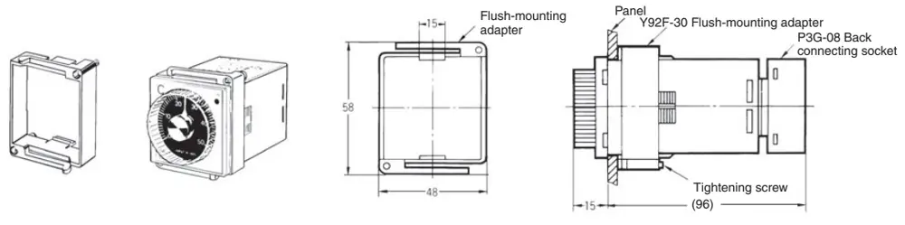
Dimensions
Note: All units are in millimeters unless otherwise indicated.
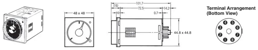
Dimensions with Flush-mounting Adapter(Accessory),and Back Connecting Socket(Sold Separately)
■ Accessories (Order Separately)
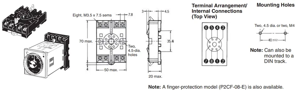
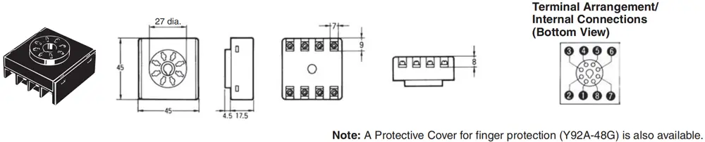
Connection Sockets
P2CF-08 Front Connecting Socket
P3G-08 Back Connecting Socket (for Flush Mounting)
Hard Protective Cover
A Hard Protective Cover (Y92A-48B) is available. It can be used in the following cases.
1.To protect the setting section, against dust and dirt
2.To prevent accidently changing settings by touching the front of the Controller.
3.To protect the Controller from water drips
|
Appearance |
|
|
Model |
Y92A-48B |

Safety Precautions
Refer to Safety Precautions for All Temperature Controllers.
■ Correct Use
Mounting
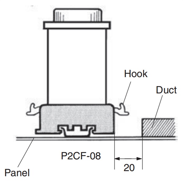
Track Mounting (E5C2 with P2CF-08)
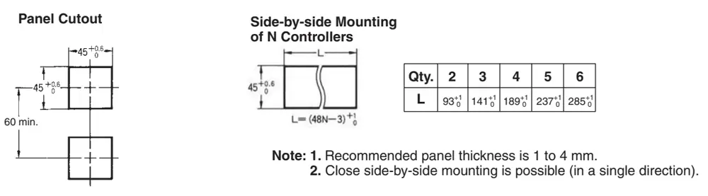
When mounting two or more E5C2 models with track-mounting sockets, leave a space of approximately 20 mm on both sides of the sockets where hooks are located.
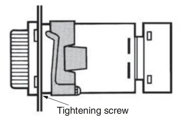
Flush Mounting
Insert E5C2 into the square hole of the panel and insert an adapter from the back so that there will be no space between E5C2 and the panel. Then, secure the E5C2 with a screw.
The P3G-08 can be wired in the same way as the P2CF-08.
Dismounting
If flush mounted, loosen the screw of the adapter and disengage the hooks for dismounting.
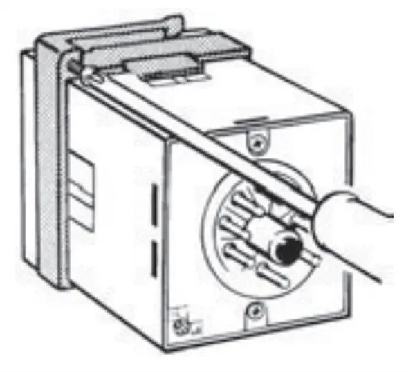
Temperature Setting
Do not turn the temperature setting knob of the E5C2 with excessive force, otherwise the stopper of the knob may break.
Others
1.Do not remove the housing of the E5C2, otherwise the housing may break.
2.To clean the surface of the E5C2, use a soft cloth wet with neutral detergent or alcohol. Do not use any organic solvent, such as paint thinner or benzine, strong acid or strong alkali to clean the surface of the E5C2, otherwise the surface of the E5C2 will become damaged.