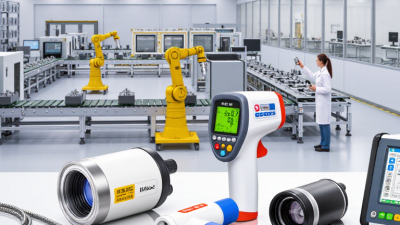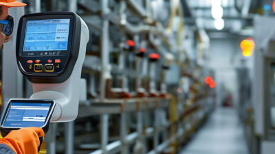
Choosing the right Temperature Instrument affects product quality, worker safety, energy use, and maintenance costs. A small reading error can spoil a refrigerated shipment or distort a laboratory result. The best choice depends on the material, temperature range, response time, accuracy, and working environment. A probe used in hot oil needs different protection than one placed inside a clean water tank.
This guide presents ten practical tips for making a confident selection. It considers contact and non-contact measurement, calibration requirements, sensor materials, display visibility, data logging, and installation limits. Real workplaces are rarely perfect. Steam may cloud an infrared lens, vibration may loosen a connection, and a low-cost sensor may drift sooner than expected. These details deserve attention before purchase.
Experience shows that specifications alone can mislead. A temperature instrument may claim excellent accuracy, yet perform poorly when installed near airflow or electrical interference. Reliable decisions require comparison with operating conditions, manufacturer documentation, and recognized calibration practices. Ask how the instrument will be checked after six months, not only how it performs on day one.
Small details matter.
The discussion also acknowledges practical trade-offs. Faster response can reduce stability, while advanced features may increase training demands. No instrument suits every application. By examining each factor carefully, readers can avoid expensive replacements and choose equipment that delivers dependable measurements over time.
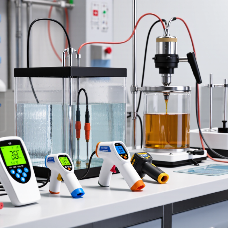
Define the process before comparing instruments. Record the normal range, minimum and maximum excursions, required accuracy, response time, and installation environment. A sensor rated from 0°C to 100°C may fail near a 180°C cleaning cycle. That detail matters. NIST Technical Note 1297 states that a coverage factor of k=2 represents approximately 95% coverage. Therefore, separate measurement accuracy from calibration uncertainty. For reference, IEC 60751 gives Class A platinum RTDs a tolerance of ±(0.15 + 0.002|t|)°C. Tight specifications cost more, but loose ones can hide process drift.
Response time needs practical testing. A fast probe can track a sudden change, yet it may create unstable readings in turbulent flow. A slower, protected probe may offer better durability. Compare the manufacturer’s stated response time using the same test conditions. Do not compare “time constant” with “time to 90% response” as if they were identical. They are not. I have seen teams select impressive accuracy, then install the sensor behind thick insulation. The specification looked excellent on paper, but the measurement lagged.
Process compatibility includes pressure, vibration, moisture, chemicals, hygienic demands, and electrical noise. Check wetted materials and sealing methods carefully. The International Society of Automation recommends documenting operating conditions before instrument selection. That step is often skipped. It should not be. Leave a realistic margin around the stated range, and verify calibration access before approval.
10 Tips for Choosing the Right Temperature Instrument?
Type K thermocouples cover approximately −200 to 1,260°C in many industrial specifications. That range looks impressive. It is not the whole story. NIST Monograph 175 lists Type K reference data across a broader temperature scale, including voltage values used for calibration. Near room temperature, its output is only about 41 microvolts per degree Celsius. Small electrical errors can therefore become visible temperature errors.
IEC 60584-1 defines Type K tolerances and reference tables for thermocouple performance. For example, Class 1 accuracy can be ±1.5°C or ±0.004 times the measured temperature, depending on the range. At 1,000°C, that percentage equals 4°C. A display showing one decimal place may suggest more certainty than the sensor provides. I have seen this mistake during equipment checks.
Choose the sheath and junction carefully. A grounded junction responds quickly against a metal surface, while an insulated junction reduces electrical interference. In oxidizing air, Type K wires usually perform well, but sulfur, reducing atmospheres, vibration, and repeated thermal cycling can accelerate drift. ASTM E230/E230M also stresses calibration, extension wire compatibility, and reference-junction control. Do not treat the −200 to 1,260°C range as a guaranteed result. Probe construction, installation, and calibration matter just as much. One practical check remains useful: compare the installed sensor with a traceable reference at several operating points, not only at room temperature.
| No. | Selection Criterion | Technical Considerations | Recommended Sensor or Instrument Choice | Practical Verification |
|---|---|---|---|---|
| 1 | Define the temperature range | Select an instrument whose rated range covers the lowest and highest expected temperatures, including short-term excursions and start-up conditions. | A Type K thermocouple is suitable for many general-purpose applications and covers approximately −200 to 1,260°C, depending on construction, insulation, and operating conditions. | Leave a practical measurement margin rather than operating continuously at the sensor’s maximum rating. |
| 2 | Match the sensor technology | Thermocouples are rugged and respond quickly; RTDs generally provide better stability and accuracy over moderate ranges; thermistors are highly sensitive over narrower ranges. | Use Type K for wide-range industrial measurement, an RTD such as Pt100 when stability is the priority, or a thermistor for compact low-to-moderate temperature sensing. | Compare the required range, accuracy, response time, durability, and replacement cost before selecting the technology. |
| 3 | Check required accuracy | Total error includes sensor tolerance, instrument accuracy, extension wire effects, installation error, and calibration uncertainty. | Choose a calibrated probe and compatible input module. For Type K, verify the applicable tolerance class and the measuring system’s stated accuracy. | Review the complete system accuracy, not only the accuracy printed on the display or sensor datasheet. |
| 4 | Evaluate response time | A smaller sensing junction usually responds faster, while a larger probe offers greater mechanical strength and may tolerate harsher conditions. | Select a grounded or exposed junction for faster response when electrical isolation is not essential; choose an ungrounded junction when isolation is required. | Consider probe diameter, sheath material, mounting method, airflow, and the thermal mass of the process. |
| 5 | Consider the operating environment | Moisture, vibration, abrasion, corrosive chemicals, pressure, and mechanical shock can shorten sensor life or create unstable readings. | Use an appropriately sheathed probe, sealed connection, and process fitting. Type K wire and insulation must be selected for the actual environment. | Confirm chemical compatibility, pressure rating, ingress protection, and mechanical load requirements. |
| 6 | Verify material compatibility | At elevated temperatures, sheath oxidation, contamination, drift, and thermocouple wire degradation may affect measurement reliability. | Select sheath and insulation materials rated for the process. For high-temperature Type K service, use suitable mineral-insulated or ceramic-protected construction where appropriate. | Check the continuous operating temperature, intermittent peak temperature, atmosphere, and expected service life. |
| 7 | Account for electrical interference | Low-level thermocouple signals can be affected by electromagnetic interference, ground loops, poor shielding, or incorrect polarity. | Use twisted, shielded thermocouple cable, correct Type K extension or compensating cable, proper grounding, and an input with cold-junction compensation. | Route sensor wiring away from motors, variable-frequency drives, power cables, and switching equipment. |
| 8 | Confirm installation and sensor placement | The sensing point should represent the process temperature and should not be dominated by pipe walls, ambient air, radiant heat, or dead zones. | Insert the probe sufficiently into the process and use a thermowell or compression fitting when protection, replacement, or pressure containment is needed. | Avoid placing the sensing junction too close to an inlet, outlet, heater, or uninsulated surface unless that is the intended measurement point. |
| 9 | Plan calibration and maintenance | Thermocouples can drift due to contamination, thermal cycling, mechanical damage, and long-term exposure to high temperatures. | Choose an instrument and probe that can be tested against a traceable reference or checked with a suitable calibrator over the relevant range. | Set inspection intervals according to process risk, temperature severity, historical drift, and regulatory requirements. |
| 10 | Review signal and integration needs | The instrument must support the correct thermocouple type, input configuration, display units, alarm functions, and communication method. | Confirm Type K support, cold-junction compensation, °C/°F selection, alarm outputs, data logging, and any required analog or digital interface. | Verify connector polarity, wiring standards, software configuration, power requirements, and replacement-part compatibility. |
| Selection note: Temperature ranges are approximate and depend on sensor construction, insulation, wire gauge, junction design, atmosphere, accuracy requirements, and instrument limitations. Always use the applicable technical standard and the manufacturer’s rated specifications for the final design. | ||||
10 Tips for Choosing the Right Temperature Instrument?
Quantify Accuracy: IEC 60751 Class A RTDs Allow ±(0.15 + 0.002|t|)°C
When selecting an RTD, check the tolerance at the actual process temperature. IEC 60751 Class A permits ±(0.15 + 0.002|t|)°C, where t is temperature in Celsius. At 100°C, the permitted sensor error is ±0.35°C. At -50°C, it becomes ±0.25°C. Small numbers matter when a control loop protects product quality.
Do not confuse RTD class accuracy with total measurement accuracy. The transmitter, lead resistance, connectors, and installation can add more error. A three-wire circuit may reduce lead effects, while a four-wire circuit can provide better resistance measurement. Shielded wiring also helps in electrically noisy areas. Keep the sensor away from heat leaks and poor contact points.
Test it in realistic conditions. A dry calibration bath may not reveal vibration, moisture, or slow thermal response. Record the reference instrument, test temperature, and observed deviation. Then review the data against the Class A limit. A quick spreadsheet helps. It can still hide wiring mistakes. I have seen carefully specified sensors lose accuracy because the terminal connection was loose. The standard gives a strong baseline, but the complete measurement chain deserves equal attention.
Class A RTDs allow a maximum tolerance of ±(0.15 + 0.002|t|)°C, where t is the measured temperature in degrees Celsius.
The chart shows how the allowable absolute tolerance increases as the measured temperature moves farther from 0°C.
A reliable temperature instrument begins with verified calibration, not a low purchase price. ISO/IEC 17025:2017 requires competent laboratories to control methods, equipment, uncertainty, and traceability. Ask for an accredited calibration certificate. Check the laboratory’s scope, measurement range, uncertainty, and certificate number. Traceability should connect the result through documented comparisons to the SI, as explained by the BIPM SI Brochure, 9th edition. A certificate alone proves little.
A 12-month calibration interval is a useful starting point, not a universal rule. ILAC G24:2022 recommends considering usage, environmental conditions, stability, risk, and historical drift. NIST Technical Note 1297 also stresses evaluating measurement uncertainty instead of treating every result equally. In practice, record the instrument’s readings before and after calibration. A probe used daily beside hot process tanks may need a shorter interval. A stable reference thermometer used monthly may justify longer verification, if evidence supports it. That assumption can fail.
Keep an adjustment history. Watch for repeated bias near the upper range. During one review, a team found clean certificates but ignored a damaged cable near a washdown area. The next reading was wrong. Calibration was current, yet confidence was not. Twelve months should be reviewed after every failure, repair, relocation, or major temperature excursion. Calibration records need dates, standards, results, uncertainty, and technician identification. Vague records create avoidable doubt.
A temperature instrument should fit the installation, not merely match the datasheet.
Check the process connection, probe length, ambient temperature, and available maintenance space. A cramped cabinet can turn routine calibration into a frustrating task. Leave room for tools and cable bends.
IP67 protection offers dust-tight construction and temporary immersion resistance under defined test conditions.
It does not automatically protect against high-pressure washdown or corrosive chemicals. Confirm the enclosure material and sealing method before installation. Small details matter.
A 4–20 mA output remains practical for long cable runs and industrial control systems.
The live-zero signal helps distinguish a low reading from a broken circuit. Still, verify loop power, load resistance, grounding, and isolation requirements. I have seen installations fail because the signal was correct, but the receiving input was incompatible.
Purchase price tells only part of the story.
Compare calibration intervals, replacement sensors, wiring labor, energy use, and the cost of process interruption. A lower-priced instrument may require more frequent checks. That choice can become expensive over several years. Ask whether local technicians can service it and whether spare parts remain available.
Keep records of drift, failures, and cleaning time. These records often reveal value better than a sales estimate. Some assumptions will be wrong. Review them after the first operating season.