Triac Thyristor and its Application in SSR Solid State Relays: Selection Guide
In the field of power electronics control, the triacis a core device for achieving contactless switching control of AC circuits. With its bidirectional conduction, rapid response, and high voltage and current resistance, it has become the core power switching element of solid state relays (SSRs), widely used in industrial control, home appliances, lighting, and other fields.
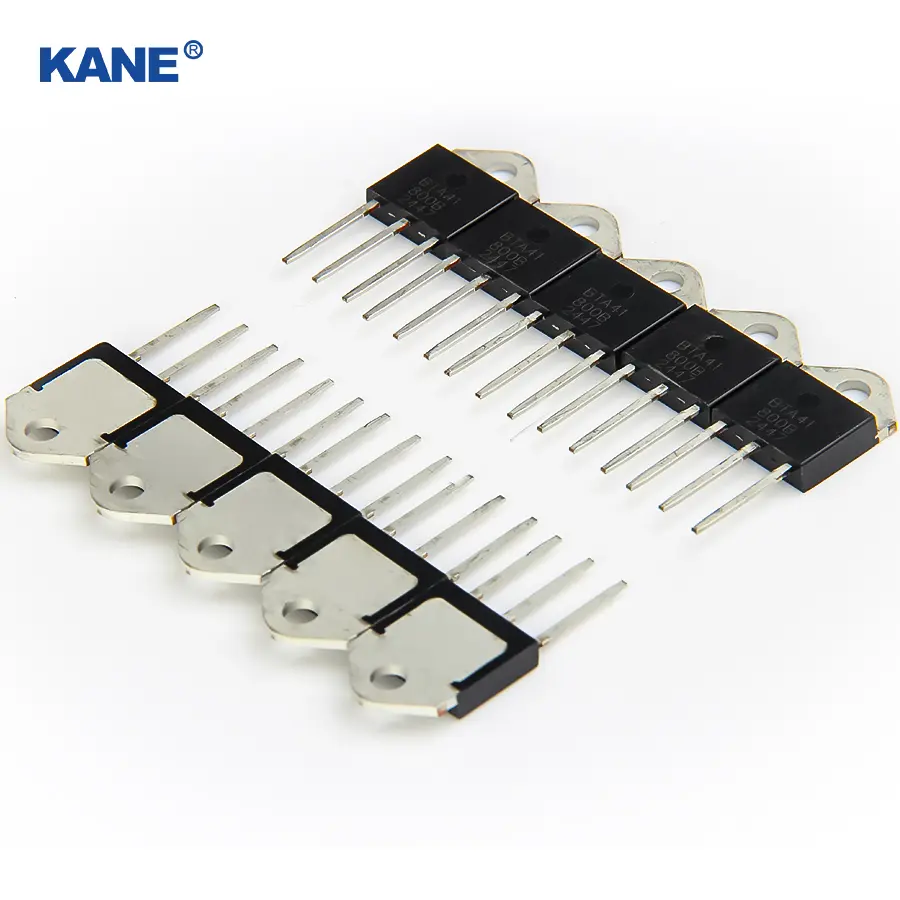
The triac has two main electrodes, T1 and T2, and one control electrode, G. Its core advantage lies in its bidirectional conduction capability—regardless of whether a positive or reverse AC voltage is applied across T1 and T2, the device will conduct as long as a suitable trigger signal is input to the control electrode; when the AC current crosses zero, it automatically cuts off without an additional turn-off signal. Compared to traditional electromagnetic switches, it has no mechanical contacts, eliminating arcing and mechanical wear. It also features fast switching speed, strong anti-interference capability, and small size, significantly improving equipment stability and lifespan, perfectly meeting the control requirements of AC circuits.
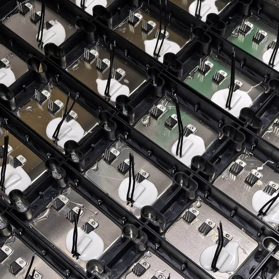
In solid state relays, the triac plays a central role as the power switch. A solid-state relay is a contactless switch that uses a weak electrical signal to control a strong electrical circuit. Its working principle involves a control circuit generating a trigger signal to drive a three-terminal bidirectional thyristor (SCR) to turn on or off, thereby controlling the power supply to the downstream load. Compared to electromagnetic relays, solid-state relays with SCRs offer advantages such as contactless operation, low noise, long lifespan, and stable operation in harsh environments. The rated current and withstand voltage of the SCR directly determine the load-carrying capacity and safe operating limits of the solid-state relay.
KANE Electric has precisely matched corresponding three-terminal bidirectional thyristor models for solid-state relays with different current specifications. The specific selection is shown in the table below:
| Solid-State Relay Specifications | Compatible Three-Terminal Bidirectional Thyristor Models |
| 10A | BTA 12 |
| 15A | BTA 16 |
| 25A | BTA 30 |
| 40A | BTA 41 |
The above selection scheme provides ample safety margin. For example, using a 12A rated current BTA 12 for a 10A SSR can effectively handle the inrush current during load startup and prevent device overload damage.
In practical applications, the load type is the key factor in selecting the solid-state relay (SSR) specification. Different loads have significantly different starting currents and operating characteristics, requiring targeted selection:
- Resistive loads: Such as resistance furnaces, incandescent lamps, and heaters. These loads have stable currents, with starting currents approximately 1.5 to 2 times the rated current. The corresponding SSR specification can be directly selected based on the load's rated current. For example, a resistance furnace with a rated current of 8A can use a 12A SSR; a 10A resistive load can use a 15A SSR.
- Inductive loads: Such as motors, transformers, and solenoid valves. These loads exhibit inductive characteristics, with starting currents reaching 3 to 5 times the rated current, and a back electromotive force is generated upon shutdown. Sufficient margin should be allowed during selection; typically, an SSR with a rated current of 3 to 5 times the load's rated current is chosen. For example, a 10A motor is recommended to use a 40A SSR; a 15A inductive load can use a 60A SSR.
- Capacitive loads: Such as capacitors and fluorescent lamps, which generate instantaneous inrush currents upon startup, with peak currents reaching 8 to 10 times the rated current. Therefore, SSRs with a rated current 8 to 10 times the load's rated current should be selected. For example, a 40A SSR is recommended for a 5A capacitive load; a 60A SSR can be selected for an 8A capacitive load.
Appropriately matching solid-state relay specifications with load type not only ensures safe and stable equipment operation but also extends device lifespan and reduces maintenance costs. In the future, with the upgrade of three-terminal bidirectional thyristor technology, the performance of solid-state relays will be further improved, providing support for intelligent control in more fields.