Aluminum Heatsinks quietly support modern electronics, from laptop processors to industrial power converters. Their purpose is simple: move heat away from sensitive components. Their performance is more complex. Aluminum conducts heat from a hot device into thin fins. Air then carries that heat into the surrounding environment. A familiar object, but not a trivial one.
Grand View Research’s 2024 Heat Sink Market report estimates that the global market will continue expanding through 2030, driven by electric vehicles, data centers, telecommunications, and compact consumer devices. The report highlights aluminum’s value because it combines low weight, corrosion resistance, manufacturability, and relatively low cost. The U.S. Department of Energy also identifies rising data-center cooling demand as an important energy-management challenge. These pressures make efficient passive cooling increasingly practical.
Thermal-management expert Dr. Alexander Bar-Cohen stated, “Thermal management is the key to the continued evolution of electronics.” His observation explains why heatsink design deserves more than a quick product comparison. Fin height, spacing, surface area, airflow, mounting pressure, and thermal-interface quality all affect results. Small gaps can create large temperature differences. That detail is often overlooked.
Aluminum Heatsinks are not automatically efficient. Copper transfers heat more effectively, while aluminum usually offers better weight and cost advantages. The best choice depends on the device, environment, and airflow. Even published thermal-resistance figures need careful interpretation. They may reflect ideal laboratory conditions, not a dusty enclosure or a restricted fan. This introduction examines how Aluminum Heatsinks work, where they perform well, and where their limitations become impossible to ignore.
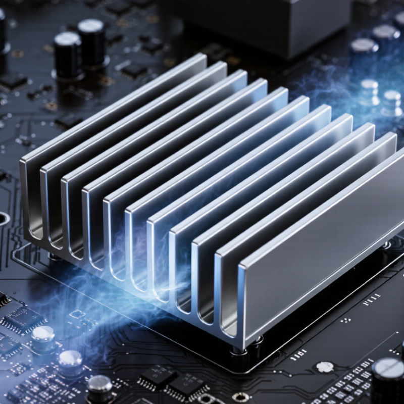
An aluminum heatsink is a passive component that helps remove heat from electronic parts. It is usually made from lightweight aluminum because the metal conducts heat well and remains practical to shape. Its solid base touches a hot component, while thin fins extend into the surrounding air. These fins create more surface area than a flat plate.
Heat moves from the component into the heatsink through direct contact. The aluminum spreads that heat across the base and fins. Air then carries the heat away through natural airflow or a fan. A heatsink does not generate cooling by itself. It only improves heat transfer. In real installations, poor contact can reduce performance sharply. A small gap, uneven surface, or excessive mounting pressure may cause trouble. Thermal compound can fill tiny surface imperfections, but it cannot fix a badly fitted heatsink.
Tips: Choose a heatsink with a base that fully covers the heat source. Keep the fins clean, because dust blocks airflow. Check the mounting method before operation. A practical test is to measure temperature under normal workload, not only at idle. Aluminum is useful, but it is not magic. For demanding equipment, fin shape, airflow direction, contact quality, and available space all matter. Engineers should also allow some temperature margin, since room conditions change during daily use.
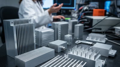
An aluminum heatsink is a passive component that transfers heat away from an electronic device. Its metal base conducts heat from the component, while the fins increase surface area so surrounding air can carry the heat away.
This comparison shows thermal conductivity at approximately room temperature. Aluminum alloys provide a useful balance of conductivity, low density, corrosion resistance, and manufacturability, making them widely suitable for finned heatsinks. Higher conductivity generally allows heat to spread more quickly through the heatsink material.
An aluminum heatsink moves heat away from an electronic component through conduction. Heat begins at the component’s hot surface and enters the heatsink base. A thin thermal interface material can fill microscopic gaps between both surfaces. Without proper contact, trapped air greatly slows heat transfer.
The aluminum base spreads heat across a wider area. Attached fins then expose more metal to surrounding air. Warm air rises between the fins, while cooler air replaces it through natural convection. Fans can increase this airflow and improve cooling performance. Heat also leaves through limited thermal radiation, although convection usually does more work.
It needs airflow.
Fin spacing matters. Very narrow channels may provide more surface area, but dust and restricted airflow can reduce their benefit. Wider fins may cool better in a passive system. Aluminum offers low weight, useful thermal conductivity, and easy shaping, but its performance depends on the alloy and design.
A practical installation requires firm, even mounting pressure. Too much pressure can damage a component, while too little creates thermal gaps. Surface flatness matters as well. In real applications, engineers should measure temperatures under the expected load instead of trusting size alone. A large heatsink can still perform poorly when airflow, contact, or orientation is overlooked. That is an easy mistake.
Aluminum heatsinks are passive cooling components that move heat away from electronic parts. They usually include a flat base, vertical fins, and a mounting system. The base contacts the hot surface, while the fins spread heat across a larger area. Aluminum is lightweight, corrosion-resistant, and easy to shape. Its thermal conductivity is lower than copper’s, but its lower weight often suits compact equipment.
Fin design strongly affects performance. Thin, closely spaced fins provide more surface area, but dust can block airflow between them. Wider gaps improve natural convection and cleaning access. Some heatsinks use straight fins, while others use pins for airflow from different directions. The mounting method also matters. Uneven pressure can leave tiny air gaps and reduce heat transfer. A thin thermal interface layer helps, though too much paste can act as insulation.
Tips: Keep the contact surface clean and flat. Check airflow direction before choosing fin spacing. Tighten screws evenly, not forcefully. In practical testing, a design may perform differently from its specification. Ambient temperature, enclosure size, and fan speed can change the result. I have found that small installation errors sometimes matter more than minor fin improvements. Measure temperatures under real operating loads, then adjust the design if needed.
| Category | Component or Design | Typical Material or Value | How It Works | Key Design Considerations |
|---|---|---|---|---|
| Basic Function | Aluminum heatsink | Thermal conductivity: approximately 150–235 W/m·K for common aluminum alloys | Conducts heat away from an electronic component and releases it into the surrounding air. | Performance depends on alloy, surface area, airflow, mounting quality, and the temperature difference between the heatsink and the air. |
| Heat Source Interface | Base plate | Typical thickness: approximately 3–10 mm for many general-purpose designs | Receives heat from the component and spreads it across the heatsink before it reaches the fins. | A flat, thick, and well-machined base reduces spreading resistance and improves contact with the heat source. |
| Heat Transfer Surface | Fins | Common fin thickness: approximately 0.5–3 mm; spacing varies by application | Increase the exposed surface area so heat can transfer from the aluminum to the surrounding air. | Fins that are too close together can restrict airflow, especially in natural-convection applications. |
| Fin Geometry | Straight-fin design | Parallel fins with a simple rectangular profile | Allows air to move through straight channels over the heated surfaces. | Suitable for both natural and forced airflow; fin orientation should support the intended airflow direction. |
| Fin Geometry | Pin-fin design | Round, square, or tapered pins arranged in an array | Provides heat-transfer surfaces in multiple airflow directions. | Useful where airflow direction is uncertain or turbulent; manufacturing and cleaning can be more complex. |
| Fin Geometry | Bonded or stacked-fin design | Separate fins attached to a base | Creates a large fin area while allowing flexible fin height, thickness, and spacing. | Bond quality and thermal contact between the fins and base affect overall thermal performance. |
| Manufacturing Method | Extruded heatsink | Commonly produced from aluminum profiles | Aluminum is forced through a shaped die to create a continuous base-and-fin profile. | Cost-effective and mechanically strong; fin height and thinness are limited by extrusion constraints. |
| Manufacturing Method | Die-cast heatsink | Cast aluminum alloy formed in a reusable mold | Produces complex shapes, mounting features, and integrated fins in a single process. | Offers design flexibility but usually has lower thermal conductivity and thicker fins than high-performance extrusions. |
| Manufacturing Method | Skived-fin heatsink | Fins cut and raised from a solid aluminum block | Creates thin, closely spaced fins with a continuous thermal path from the base. | Can provide high surface area and low interface resistance, but production cost is generally higher. |
| Thermal Interface | Thermal interface material | Thermal grease, phase-change material, pad, or thermal adhesive | Fills microscopic air gaps between the component and the heatsink base. | The layer should be thin and evenly applied; excessive thickness can increase thermal resistance. |
| Air Movement | Natural convection | Typical heat-transfer coefficient: approximately 5–25 W/m²·K | Warm air rises naturally, carrying heat away from the fins without a fan. | Requires adequate spacing and vertical fin orientation; suitable for lower-power or quiet applications. |
| Air Movement | Forced convection | Typical heat-transfer coefficient: approximately 25–100 W/m²·K or higher | A fan or system airflow moves air across the fins more rapidly than natural convection. | Provides greater cooling capacity but adds noise, power consumption, and a possible fan-maintenance requirement. |
| Surface Treatment | Anodized surface | Protective aluminum-oxide layer; black anodizing can improve radiation performance | Protects the aluminum from corrosion and can increase emissivity for radiative heat transfer. | In forced-air systems, airflow and surface area usually have a greater effect than color alone. |
| Thermal Performance | Thermal resistance | Measured in °C/W or K/W | Indicates the temperature rise required for the heatsink to dissipate one watt of heat. | Lower values indicate better cooling. The complete thermal path includes the component interface, heatsink, and ambient air. |
| Design Calculation | Estimated temperature rise | Temperature rise ≈ heat load × total thermal resistance | Provides a first-order estimate of how much hotter the component may become than the surrounding air. | For accurate results, account for airflow, contact pressure, mounting orientation, material tolerances, and operating conditions. |
| Mechanical Features | Mounting holes, clips, or threaded channels | Designed to match the component package or system chassis | Hold the heatsink firmly against the heat source and maintain consistent interface pressure. | Uneven pressure can create air gaps, while excessive pressure may damage the component or circuit board. |
| Material Comparison | Aluminum compared with copper | Aluminum: approximately 150–235 W/m·K; copper: approximately 380–400 W/m·K | Aluminum offers good thermal conductivity with lower density and cost than copper in many applications. | Copper may provide better heat spreading, while aluminum is often preferred when weight, manufacturability, and cost are important. |
An aluminum heatsink moves heat away from an electronic component. Its metal base touches the hot surface. Heat then spreads through the aluminum and reaches the fins. The fins expose more area to moving air. This allows convection to carry heat into the surrounding room. Radiation also contributes, although usually to a smaller degree.
Several factors affect aluminum heatsink performance. Aluminum alloy and thickness influence thermal conductivity. A thin, uneven base can create resistance before heat reaches the fins. Fin height, spacing, and shape also matter. Dense fins may provide more area, but they can restrict airflow. Natural convection needs wider channels. Forced airflow can support tighter spacing.
The interface between the component and heatsink deserves careful attention. Air pockets behave like insulation. A thin, evenly spread thermal interface layer works better. Mounting pressure must remain firm but should not damage the component. Ambient temperature matters too. A heatsink performs differently in a cool laboratory and inside a warm enclosure. Orientation can change natural airflow around vertical fins.
Real testing often exposes design assumptions. A calculated temperature may look safe, yet a blocked vent can raise it quickly. Dust adds another thermal barrier. Contact surfaces should be clean and flat. Measuring temperatures at several points gives more reliable evidence than checking one location. Small manufacturing differences can also change results, so performance should not be judged from geometry alone.
Aluminum heatsinks appear wherever compact electronics must release heat without adding excessive mass. They transfer heat from a device into surrounding air. Their fins increase surface area, while aluminum provides useful thermal conductivity and low weight. Extruded 6063 aluminum is common because it supports detailed fin shapes and efficient production.
Common applications include LED lighting, telecommunications equipment, computers, industrial motor drives, and electric vehicle power electronics. Inverters and onboard chargers use heatsinks to protect switches from excessive junction temperatures. The International Energy Agency reported more than 17 million electric car sales worldwide in 2024. That growth increases demand for compact thermal solutions.
Power supplies also depend on heatsinks during continuous operation. Small fans may improve airflow, but they add noise, dust exposure, and another failure point.
Data centers use aluminum heatsinks inside servers, network devices, and power systems. The U.S. Department of Energy states that cooling can represent up to 40% of data center electricity use. Thermal design therefore affects both reliability and operating cost.
A larger fin stack is not always better. Poor airflow, uneven mounting pressure, or dried thermal interface material can reduce performance sharply. Bench testing often exposes this problem. A heatsink may feel cool while the semiconductor remains dangerously hot.
Engineers should measure junction temperature, airflow, contact resistance, and load cycles instead of trusting appearance alone. Small details matter.