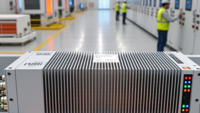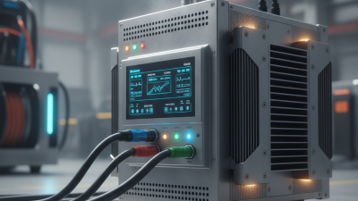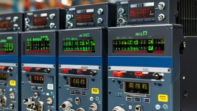
Choosing the best Thyristor Voltage Regulator in 2026 starts with the load, not the product label. A heater, transformer, and motor can react differently to the same voltage adjustment. That difference matters. Before comparing models, record the supply voltage, phase, load current, operating range, and expected changes in demand. A clear load profile is more useful than a broad claim of “high performance.”
In real installations, cabinet temperature, ventilation, wiring distance, and electrical noise can affect operation. Check the regulator’s continuous current rating and overload behavior, then compare its control method with the load’s requirements. Ask how it handles voltage fluctuations and whether its switching may introduce harmonics or electromagnetic interference. The answers should be supported by technical documentation, not just a sales description.
There is no universal best choice. A compact unit may suit a stable process, while a demanding installation may need better cooling, monitoring, and service access. Look for clear specifications, protection details, test information, and support from a qualified supplier. Also check compatibility with upstream protection and the equipment being controlled. Do not assume that a larger rating automatically means safer operation; installation conditions still matter. Datasheets can leave gaps. Confirm uncertain points with the manufacturer or a qualified electrical professional before purchase. This guide explains the practical criteria to compare, the questions to ask, and the trade-offs worth reviewing before selecting a regulator.

A thyristor voltage regulator must match the supply it will actually receive, not just the voltage listed on a machine label. Check whether the input is 50 Hz, 60 Hz, or compatible with both. Frequency mismatch can affect control behavior and produce unexpected operation. Small details matter. Confirm the supply voltage and whether it is measured phase-to-neutral or phase-to-phase.
Next, match the regulator’s phase configuration to the installation. A single-phase unit cannot serve a three-phase load simply because its voltage rating looks right. Check the load current in amperes, including whether the rating is continuous and under what cooling conditions. Motors and transformers may draw brief starting surges; heaters usually behave differently. That is not enough. Allow for inrush current and the regulator’s specified derating at higher ambient temperatures.
Read the equipment nameplate, then compare it with the regulator’s datasheet and wiring diagram. A qualified installer can confirm phase sequence, conductor sizing, and protective-device coordination before energizing the system. Ratings can be easy to misread, especially when suppliers list different voltage conventions. If the supply fluctuates, verify its real operating range rather than assuming nominal voltage tells the whole story. A careful match reduces nuisance trips, overheating, and avoidable downtime.
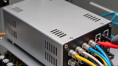
In 2026, choosing a thyristor voltage regulator starts with how the load uses power. Phase-angle control adjusts voltage during each AC cycle. It responds quickly and suits loads needing smooth, continuous adjustment, such as lighting or some motor applications. The trade-off is a chopped waveform, which can increase electrical noise and harmonics. Check equipment compatibility carefully. Fast response is useful.
Burst-firing control switches complete AC cycles on and off, usually near the zero crossing. It is often a good fit for resistive heating elements, such as an industrial oven’s heater bank. This method can reduce switching noise, but power arrives in pulses. A sensitive process may experience temperature swings, while changes in load can affect supply stability. The details matter.
I would not choose from the load label alone; real installations can behave differently. Check the load’s resistance or inductance, required response speed, current rating, and thermal behavior. For example, a slow-heating furnace may tolerate burst firing, while a process demanding rapid output changes may favor phase-angle control. Review the regulator’s specifications and measure the supply during commissioning. A small test under operating conditions can reveal issues that calculations miss. That step is easy to overlook.
How to Choose the Best Thyristor Voltage Regulator in 2026?
Start with the load’s true RMS current, not just its nameplate figure. Measure or calculate it at the highest expected operating level. For phase-controlled loads, current waveforms may be distorted, so confirm how the SCR datasheet defines its current rating. A rating quoted for a cool case or ideal waveform may not suit a warm, enclosed panel. Leave practical margin.
Inrush needs separate attention. Transformers, lamps, and cold heating elements can draw brief currents far above steady-state demand. Check the surge-current rating and I²t limit against both the pulse magnitude and duration. Repeated starts matter, too; a single surge rating does not guarantee safe cycling. That detail is easy to miss.
Then size the heatsink from actual device losses and the highest ambient temperature. Use the SCR’s conduction-loss data, then check the full thermal path: junction-to-case, interface, and heatsink-to-air resistance. Keep the junction temperature below its limit with margin, allowing for blocked vents, dust, and nearby hot components. Real installations are messier than the spreadsheet. I would recheck the calculation after measuring the enclosure temperature under load; airflow assumptions are often optimistic.
When choosing a thyristor voltage regulator in 2026, check harmonic limits alongside voltage, current, and control range. IEC 61000-3-2 generally covers equipment drawing up to and including 16 A per phase. IEC 61000-3-12 generally applies above 16 A and up to 75 A per phase on public low-voltage systems. The right category depends on the equipment’s rated input current and connection conditions, not just the regulator’s label.
Thyristor phase-angle control can distort the current waveform, especially when a heater runs at reduced output. That distortion may affect nearby equipment or push a site’s harmonic levels beyond its design limits. Ask for test data across the intended load range, not only at full power. Check the applicable standard edition and installation conditions with a qualified engineer; a tidy datasheet may still leave gaps.
Tips: Confirm whether your load is single-phase or three-phase, then match its input current to the relevant standard. Request harmonic measurements at typical operating points. Look for current waveform or total harmonic distortion data, and verify measurement conditions. Small loads can behave differently in a real panel. Check the actual setup.
Check the applicable harmonic-emission standard based on the equipment’s input current per phase.
IEC 61000-3-2 applies to equipment rated at ≤16 A per phase; IEC 61000-3-12 covers equipment rated above 16 A and up to 75 A per phase. These ranges identify the applicable standard, not harmonic pass/fail limits. Actual limits depend on the equipment category and test conditions.
When choosing a thyristor voltage regulator in 2026, treat IEC 60947-4-3 and IEC 60204-1 as practical checks, not just labels on a datasheet. IEC 60947-4-3 addresses semiconductor controllers and contactors for non-motor loads. Ask for documentation identifying the tested device configuration, operating conditions, and applicable edition. A certificate alone may not describe how the regulator behaves inside your panel.
IEC 60204-1 focuses on electrical equipment of machinery. Check how the proposed installation supports protective bonding, overcurrent protection, isolation, and clear fault identification. Confirm that the regulator’s current rating suits the actual load, including start-up demands, and that its heat can escape. A crowded cabinet can turn a suitable unit into an overheating problem. Small details matter. Review wiring diagrams, terminal ratings, required fusing, and cooling guidance with the machine’s electrical designer. Also verify which protective measures belong to the regulator and which must be provided by the surrounding system. Standards compliance does not replace a site-specific risk assessment. During commissioning, measure temperatures under representative load and test the documented fault responses. Paperwork helps, but it cannot reveal every installation gap.
| Selection Dimension | What to Check | Practical Selection Guidance | Evidence to Request or Verify | Safety and Standards Relevance |
|---|---|---|---|---|
| Load type | Confirm whether the load is resistive, transformer-based, or another non-motor AC load. | Check that the regulator’s stated operating mode and load category match the actual load. Transformer loads may have high inrush current and require specific suitability confirmation. | Manufacturer’s ratings, load-category information, application guidance, and approved wiring diagram. | IEC 60947-4-3 addresses AC semiconductor controllers and contactors for non-motor loads. Confirm that the device’s intended use falls within its declared scope. |
| Supply voltage and frequency | Compare the system’s nominal voltage, frequency, phase configuration, and permitted supply variation with the regulator’s ratings. | Select a unit rated for the actual supply system; do not assume that a single-phase rating covers a three-phase installation. | Nameplate or datasheet values, connection diagram, and specified operating limits. | Verify that the complete machine’s electrical design is suitable for its supply conditions under the applicable requirements of IEC 60204-1. |
| Continuous current and load rating | Check rated operational current, load current, conductor size, and enclosure temperature. | Allow for the installation’s ambient temperature, ventilation, mounting arrangement, and duty cycle. Use the manufacturer’s derating data rather than relying on a headline current rating alone. | Rated-current conditions, derating curves, thermal data, and terminal conductor specifications. | Product ratings and machine wiring must be considered together; the regulator’s rating does not by itself establish the rating of the complete circuit. |
| Control method and output range | Identify the required control input and whether the application needs phase-angle control, burst firing, or another supported method. | Match the input signal and control behavior to the process. Check minimum and maximum output, control stability, and compatibility with the load. | Control-input specification, output characteristics, configuration instructions, and functional test results. | Confirm that the control circuit and its interfaces are integrated safely into the machine’s electrical equipment. |
| Overcurrent and short-circuit coordination | Determine what upstream protective device is required and how the semiconductor device is protected against short-circuit current. | Use the protection type and ratings specified by the regulator manufacturer. Do not assume that a semiconductor device can interrupt a short circuit or replace an upstream protective device. | Coordination tables, recommended fuse or circuit-breaker data, short-circuit ratings where declared, and installation instructions. | Verify protective-device selection and circuit coordination for the intended installation. IEC 60947-4-3 product information and IEC 60204-1 machine-level design considerations are relevant. |
| Overtemperature protection | Check for temperature monitoring, thermal shutdown behavior, and any required heatsink or airflow. | Provide the specified cooling and keep ventilation paths clear. Confirm how the machine responds to an overtemperature alarm or trip. | Thermal limits, heatsink requirements, alarm or trip description, and functional test procedure. | Assess the regulator’s thermal protection as part of the machine’s risk controls; it does not replace correct installation or system-level protection. |
| Safe isolation and maintenance | Determine how the machine is disconnected from its electrical supply for servicing. | Provide an appropriate supply-disconnecting arrangement in the machine design. A semiconductor regulator may allow leakage current or fail in a conducting state, so do not treat its control signal as an isolation device. | Machine circuit diagrams, disconnecting-device specifications, isolation procedure, and maintenance instructions. | IEC 60204-1 addresses electrical equipment of machinery, including machine-level supply disconnection and related safety design. Verify the applicable requirements for the specific machine. |
| EMC and electrical noise | Check switching method, conducted or radiated emissions information, and susceptibility requirements for nearby equipment. | Follow the installation guidance for wiring separation, grounding, filtering, and cable routing. Validate the finished installation where required by the application. | EMC test information or declarations, filter recommendations, grounding instructions, and installation guidance. | Assess EMC at the relevant equipment or machine level; a component document alone may not demonstrate compliance of the complete installation. |
| Environmental and enclosure conditions | Review ambient temperature, humidity, contamination, altitude, vibration, and enclosure protection needs. | Choose a mounting location and enclosure that stay within the regulator’s stated limits. Check any altitude or temperature derating requirements. | Environmental ratings, installation clearances, enclosure instructions, and derating information. | Confirm that the installed regulator and machine enclosure are suitable for the intended operating environment. |
| Documentation and conformity | Check that product markings and technical documents identify the applicable ratings, intended use, and installation requirements. | Review the exact product model and configuration; confirm that supplied documentation corresponds to the unit being installed. | Rating label, technical documentation, conformity information where applicable, and current installation instructions. | IEC 60947-4-3 and IEC 60204-1 have different scopes: one concerns the relevant semiconductor switching product category, while the other concerns machinery electrical equipment. Verify applicability and edition with the project’s regulatory requirements. |
Important: Use this table as a selection checklist, not as a declaration of conformity. The applicable standard edition, legal requirements, protection coordination, and final acceptance criteria depend on the product, machine, installation location, and project specification.