Choosing a Rotary Encoder is less about selecting the highest resolution and more about matching the sensor to real operating conditions. A compact knob on a control panel has different needs from a motor shaft exposed to vibration, dust, or frequent speed changes. Shaft diameter, mounting space, rotation speed, temperature, and cable length all affect the decision. Small details matter.
Resolution determines how finely position changes can be detected, but higher counts are not always useful. An incremental encoder tracks movement through pulses and may need a reference point after startup. An absolute encoder reports a position value, which can help when a machine must know its location immediately. Noise changes everything. Long cables, nearby drives, and poor grounding can distort signals, so output type and electrical compatibility deserve careful review.
For reliable selection, compare the encoder’s mechanical limits and electrical specifications with the application’s actual requirements. Check allowable shaft loads, ingress protection, supply voltage, output format, and the controller’s input capability. Mounting alignment matters too; even a suitable encoder can wear early if its shaft is forced off-center. In practice, the first choice is not always the best one. A datasheet cannot fully represent installation conditions, and that is easy to overlook. Testing a sample under realistic load, speed, and noise conditions can reveal issues before production. This guide explains how to weigh these factors and choose a Rotary Encoder that fits the machine, not just the specification sheet.
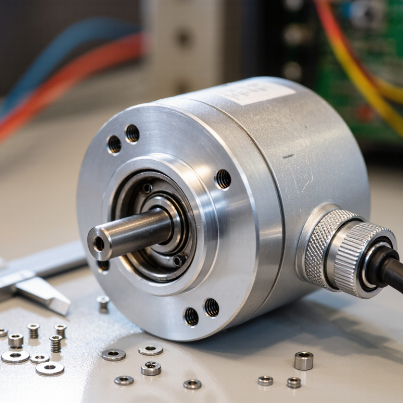
A rotary encoder measures the rotation of a shaft or knob. It converts angular movement into electrical signals that a controller can interpret. The measured information may include position, direction, and speed, depending on the encoder type and the connected electronics.
An incremental encoder reports movement as pulses. Two offset signal channels, often called quadrature outputs, let a controller determine direction by comparing which channel changes first. Count the pulses, and the system can estimate movement from a known starting point. That matters. If power is lost, the count may be lost too. An absolute encoder instead provides a coded position value, so the system can identify the shaft’s position after startup. Not always.
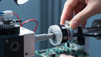
Inside the encoder, a rotating pattern passes a sensing element. Optical designs detect changes in light; magnetic designs detect changes in a magnetic field. Both can work well, but dust, vibration, mounting alignment, and operating speed affect real-world performance. A loose coupling can create readings that look erratic, even when the encoder itself is sound. I would check the signal with the intended controller before relying on a datasheet alone. A small test on the actual shaft can reveal timing or noise issues early.

A rotary encoder should match the motion you need to measure, not just the shaft it fits. Incremental encoders report movement as pulses, making them useful for speed feedback and relative positioning. However, they may lose their position reference after power is removed. Absolute encoders provide a distinct position value, which helps when a machine must know its angle immediately after restart. That added certainty can mean greater cost or system complexity.
The sensing method matters, too. Optical encoders can offer fine resolution in clean, controlled equipment, while magnetic designs often tolerate dust, vibration, and less forgiving surroundings. Check the required resolution, maximum shaft speed, output signal, and controller compatibility. A conveyor moving steadily may need reliable speed feedback more than extremely fine position data. A joint that must return to a precise angle has different needs. There is no universal winner; selection can be less tidy than a specification sheet suggests.
Tips: Define the motion first: continuous rotation, indexed movement, or absolute angle. Then check the installation space and operating environment. Test the encoder with the actual controller and cable length when possible. Small signal problems can become frustrating faults. Don’t choose resolution alone; higher counts do not automatically improve real-world accuracy.
Choosing a rotary encoder begins with the motion your system needs to measure. For a slow indexing table, modest resolution may be enough. A fast motor or small positioning step may require many more counts per revolution. Check how the controller interprets those counts, including any quadrature multiplication. A stated resolution can look generous on paper but mean something different in the finished system.
Resolution and accuracy are not the same. Resolution describes the smallest reported change; accuracy describes how closely the measured angle matches the real angle. Bearing play, shaft alignment, mounting runout, and temperature can all affect the result. A few arcminutes of error may matter on a precision axis. It may not matter on a conveyor. Test the encoder in its actual mounting arrangement, not only from a data sheet. Small details count.
Then match the output to the control hardware. Incremental A/B signals suit systems that track movement from a reference point, while an index pulse can help establish that reference. Absolute outputs report position directly after startup, but check the protocol, voltage levels, and update rate. Long cables near motor wiring may call for differential signals and careful grounding. It is tempting to choose the highest resolution available. That can increase data load without improving useful positioning. A neat specification sheet can still miss a loose coupling or noisy cable. Test both.
Start with the shaft and mounting space, not just the resolution. A hollow-shaft encoder may slide onto an existing shaft, while a solid-shaft model usually needs a coupling. Measure shaft diameter, available depth, and alignment tolerance before choosing. Fit matters. Even slight misalignment can add mechanical stress or cause inconsistent readings. Check how the encoder will be secured and whether it can be accessed for service.
The operating environment affects reliability. Dust, oil mist, vibration, and moisture can all influence housing and sealing requirements. For a washdown area, confirm the enclosure’s stated protection level rather than relying on appearance. Condensation is easy to overlook. Temperature swings can affect both electronics and mechanical clearances, so compare the operating range with real conditions near the machine. That detail bites.
Then match the output interface to the controller. Incremental encoders commonly provide pulse signals, but the controller must support the signal type and voltage. An absolute encoder reports position directly, which can help after a power interruption, though the communication protocol must also be compatible. Check cable length, connector style, and electrical noise near motors or drives. A specification sheet may not capture every installation quirk; leave room to verify fit and signal quality during commissioning.
A rotary encoder is compatible only when its electrical signals and mechanical fit match the controller and application. Check whether the controller accepts incremental or absolute signals, then confirm the required interface and voltage levels. A 5 V encoder may not connect safely to a 3.3 V input without suitable signal conditioning. Small details matter.
Compare the encoder’s pulses per revolution with the controller’s input bandwidth and the speed of the machine. For example, a high-resolution encoder on a fast shaft can produce pulses faster than the controller can read. Check the wiring diagram, output type, cable length, and shielding requirements. Also verify shaft diameter, mounting space, coupling alignment, and operating temperature. A mismatch may work briefly, then cause missed counts or unstable readings. It is easy to focus on resolution and overlook signal frequency; that deserves a second look.
Tips: Read the controller manual before ordering. Confirm pin assignments and signal levels with a meter, then test at the expected shaft speed. Measure twice. If possible, run a short trial with the actual cable and load, since bench tests may not reveal electrical noise or vibration.
| Compatibility Dimension | Example Application Requirement | What to Verify on the Encoder | What to Verify on the Controller | Practical Verification |
|---|---|---|---|---|
| Measurement type | Incremental position and direction feedback | Confirm incremental outputs, typically A and B in quadrature; check whether an index Z pulse is needed. | Confirm support for quadrature counting and, if required, index capture or homing. | Rotate the shaft slowly and confirm that the controller reports direction changes and a repeatable index event. |
| Resolution and counting convention | A target of 8,192 counts per revolution using a 2,048 PPR encoder and x4 quadrature decoding | Check pulses per revolution (PPR) and whether the specification uses cycles, pulses, or counts. A and B x4 decoding produces four counts per cycle. | Check selectable x1, x2, or x4 decoding and the counter's permitted count range. | Turn the shaft one full revolution and compare the reported count with the expected value, accounting for the controller's decoding mode. |
| Output circuit and signal level | Logic-level input signals over a short cable run | Identify the output type—such as push-pull, open-collector, or differential line driver—and its voltage and current specifications. | Confirm the input's supported voltage, input current, and circuit type. Open-collector outputs may require a compatible pull-up. | Compare the encoder's output and the controller's electrical specifications before wiring; do not connect signals based only on connector shape. |
| Supply voltage and current | A 5 V DC encoder supplied from the control cabinet | Check the rated supply range, current consumption, and whether output levels depend on supply voltage. | Confirm the available supply voltage and current capacity, including the total load of connected devices. | Verify voltage at the encoder terminals under load and ensure the supply remains within the encoder's specified range. |
| Maximum speed and input bandwidth | 2,048 PPR at 3,000 rpm | Check the encoder's maximum operating speed and maximum output frequency. For this example, the channel frequency is 2,048 × 3,000 ÷ 60 = 102.4 kHz. | Confirm that the selected input can accept the signal frequency and edge rate. At x4 decoding, the example produces up to 409,600 counts per second. | Check the controller manual for frequency limits in the selected counting mode and allow margin for speed variation and signal transitions. |
| Signal transmission and cable | A machine with electrical noise or a longer cable route | Check whether the output is single-ended or differential and review the specified cable and termination requirements. | Confirm that inputs support the encoder's signaling method. Differential signals require compatible differential receiver inputs. | Use the recommended cable type and grounding practice; route encoder wiring away from motor and high-current cables where practical. |
| Interface and protocol | Absolute position over a digital interface | Check the exact interface and protocol version, bit length, data format, timing, and any required configuration. | Confirm that the controller has a compatible interface or an approved interface module and supports the same protocol details. | Verify protocol compatibility from both technical manuals; similar connector types do not establish protocol compatibility. |
| Shaft and mounting | Direct mounting to a rotating machine shaft | Check shaft diameter, shaft type, allowable radial and axial loads, mounting dimensions, and coupling requirements. | Confirm the installation space and that the mechanical arrangement does not exceed the encoder's load limits. | Compare mechanical drawings and use a suitable coupling or mounting method to avoid misalignment and excessive shaft loading. |
| Environmental rating | Operation near dust, moisture, or elevated ambient temperatures | Check the specified operating temperature range and enclosure protection rating for the installed configuration. | Confirm that the installation location and any required connector or cable protection meet the application's conditions. | Assess the complete installation, including connectors and cable entries; an enclosure rating applies only under its stated conditions. |
| Controller setup and final test | Reliable position feedback after installation | Confirm pin assignments, signal labels, required accessories, and the encoder's configuration settings. | Set the correct input mode, filter, scaling, direction, and counting method; check for input diagnostics. | Test direction, one-revolution count, index behavior if used, and operation across the application's speed range before commissioning. |